Camera calibration device and method, and vehicle

The technology of a calibration device and a calibration method, which is applied in the field of vehicles, can solve the problems of increasing calibration work burden, occupying a large space, and spending time and labor, thereby achieving the effect of simplifying calibration work.

Inactive Publication Date: 2010-09-15
SANYO ELECTRIC CO LTD
View PDF4 Cites 20 Cited by
  • Summary
  • Abstract
  • Description
  • Claims
  • Application Information

AI Technical Summary

Problems solved by technology

Since the size of such a calibration pattern is, for example, twice the size of the vertical and horizontal dimensions of the vehicle, it takes up a large space during the calibration work, and it takes time and labor to prepare the calibration environment, thereby increasing the burden on the overall calibration work.

Method used


Image

  • Camera calibration device and method, and vehicle
  • Camera calibration device and method, and vehicle
  • Camera calibration device and method, and vehicle

Examples


no. 1 example 》

[0111] First, the first embodiment will be described. Figure 11 It is a flowchart showing the flow of the process of specifying the arrangement position of the calibration pattern. In the first embodiment, the alignment work of the calibration pattern is supported by sound notification. Figure 11 The processing of step S11 is executed by each camera and the main control unit 10 , and the processing of steps S12 to S14 is executed by the main control unit 10 . The subject of the processing in steps S15 and S16 will be described later. The processing of steps S11 to S16 is in progress Figure 10 Execute before the processing of step S2, and execute after proceeding to step S16 Figure 10 The processing of steps S2 to S4 (or the processing of steps S1 to S4).

[0112] right Figure 11 The processing content of each step shown will be described. First, the operator moves to step S11 after arranging each calibration image around the vehicle 100 . At this time, the operator...

no. 2 example 》

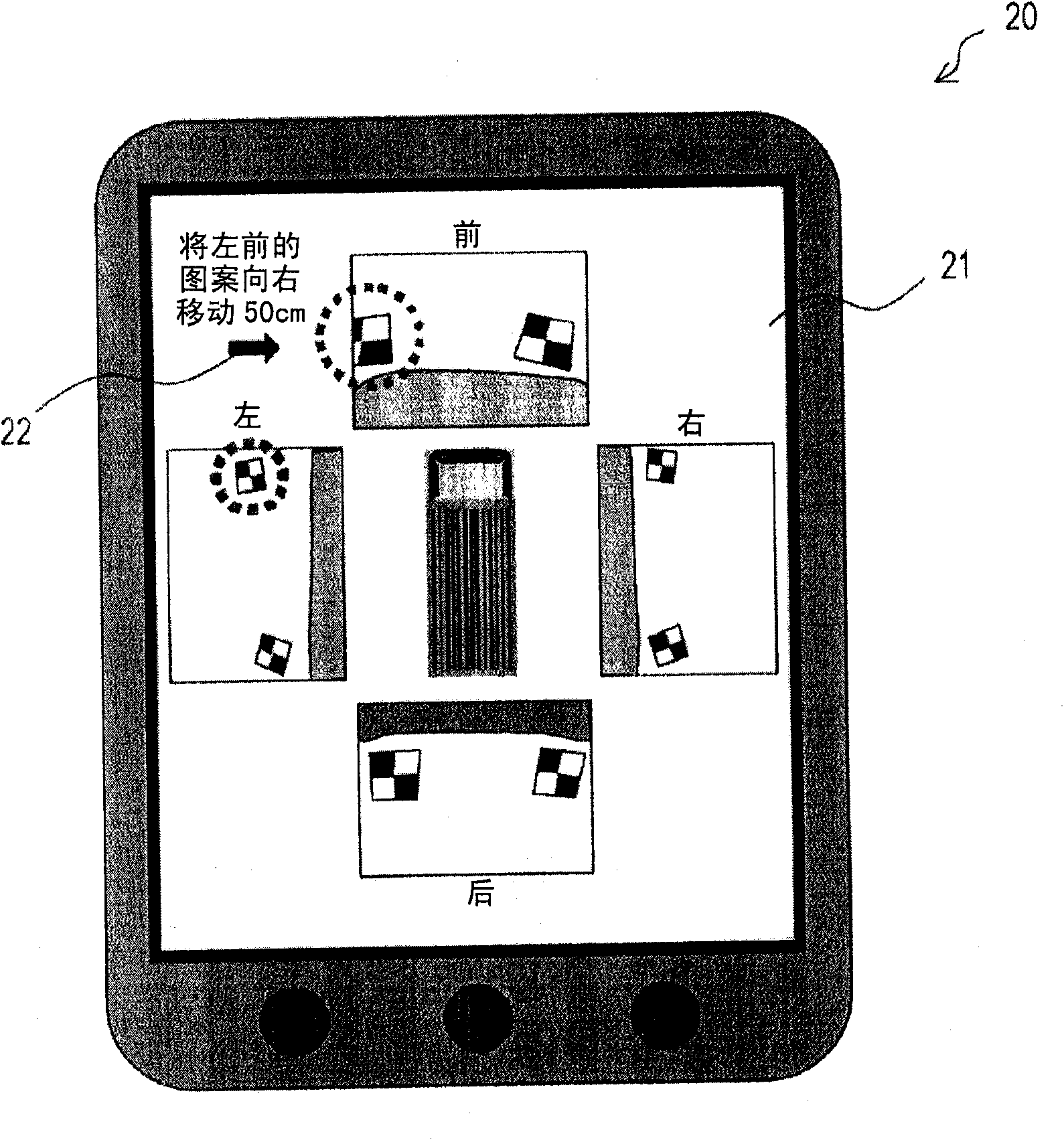
[0142] The notification performed in steps S15 and S16 may be realized not by audio output but by video display. This image shows the Figure 5 The display device 11 or any other display device. An embodiment realizing notification of such video display is taken as a second embodiment. The second embodiment differs from the first embodiment in that the image display is used for the work of determining the arrangement position of the calibration pattern, and is the same as the first embodiment in other respects. Therefore, only the differences from the first embodiment will be described.

[0143] Figure 18It is a plan view of the appearance of the mobile terminal device 20 that the operator should carry when calibrating the camera. A display device (video display device) constituted by a liquid crystal display panel or the like is provided in the portable terminal device 20 , and reference numeral 21 denotes a display screen of the display device. The portable terminal de...

no. 3 example 》

[0152] Next, a third embodiment will be described. In the third embodiment, a block diagram of a part that performs the process of specifying the arrangement position of the correction pattern is shown.

[0153] Figure 19 It is a block diagram of a part that performs the process of specifying the arrangement position of the calibration pattern corresponding to the first embodiment. The parts referred to by symbols 31 to 34 are set in Figure 5 In the main control unit 10 of the The voice output device 35 may be a device within the operation support system, or the voice output device 35 may be a device outside the operation support system. It can be considered that the parts referenced by symbols 31-34 form the camera calibration means. The sound output device 35 may be used as a device within the camera calibration device, or may be used as a device outside the camera calibration device.

[0154] The correction pattern / feature point detection section 31 is based on Fig...


PUM


Abstract

A camera calibration device performs camera calibration for projecting a plurality of camera images from a plurality of cameras onto a predetermined surface to combine them on the basis of the results after calibration patterns to be arranged in a common photographing area of the cameras are photographed by each of the cameras. The camera calibration device judges whether or not the calibration patterns are observed by the cameras on the basis of the photographed results. If judging that the calibration patterns are not observed, the camera calibration device creates the content of an instruction to contain the calibration patterns in the common photographing area to allow the cameras to observe the contained calibration patterns on the basis of the photographed results and notifies the instruction content to an operator who is in charge of the arrangement operation of the calibration patterns.

Description

technical field [0001] The present invention relates to a camera calibration device and a camera calibration method for realizing camera calibration processing necessary for projecting and synthesizing camera images from a plurality of cameras on a predetermined surface, and to a camera calibration device using the camera calibration device and camera calibration method. approach vehicle. Background technique [0002] In recent years, with the improvement of safety awareness, many vehicles such as automobiles are equipped with cameras (vehicle cameras). In addition, we not only display images from cameras, but also conduct research to enable people to see higher-quality images using image processing technology. One of these studies is to generate and display a bird's-eye view image as viewed from above the ground by performing coordinate transformation on the captured image. By displaying the bird's-eye view image, the driver can easily grasp the situation around the vehic...

Claims


Application Information

Patent Timeline
Patent Type & Authority Applications(China)
IPC IPC(8): H04N7/18B60R1/00B60R11/02G06T1/00
CPCG06T7/0028G06T2207/30252G06T7/002G06T2207/30204B60R11/04G06T7/85G06T7/33
Inventor 浅利圭介石井洋平
Owner SANYO ELECTRIC CO LTD
Why Eureka
Try Eureka