
A Novel Liquid Crystal Polarization Modulator and Its Detection Method

A polarization modulator and polarization modulation technology, applied in the method of image detector and image signal processing, measuring the polarization of light, instruments and other directions, can solve the problems of low modulation accuracy and many error sources, and reduce the difficulty of analysis, The effect of reducing the number of error sources, high-precision polarization modulation function

Active Publication Date: 2021-04-23
INST OF FLUID PHYSICS CHINA ACAD OF ENG PHYSICS
View PDF17 Cites 0 Cited by
  • Summary
  • Abstract
  • Description
  • Claims
  • Application Information

AI Technical Summary

Problems solved by technology

[0005] The purpose of the present invention is to provide a new type of liquid crystal polarization modulator and its detection method to solve the problem that there are many error sources in the existing liquid crystal polarization modulation module composed of two nematic liquid crystal adjustable phase retarders and a linear polarizer. The problem of low modulation accuracy

Method used


Image

  • A Novel Liquid Crystal Polarization Modulator and Its Detection Method
  • A Novel Liquid Crystal Polarization Modulator and Its Detection Method
  • A Novel Liquid Crystal Polarization Modulator and Its Detection Method

Examples


Embodiment 1

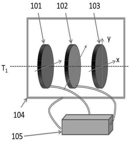
[0043] Such as Figure 1-Figure 6 As shown, a novel liquid crystal polarization modulator includes a liquid crystal polarization modulation component 201, and the liquid crystal polarization modulation component 201 includes a twisted nematic liquid crystal wave plate 101, an antiparallel nematic liquid crystal wave plate 102 and a linear polarizing plate 103. The anti-parallel nematic liquid crystal wave plate 102 is arranged between the twisted nematic liquid crystal wave plate 101 and the linear polarizer 103, the twisted nematic liquid crystal wave plate 101 is located at the front end, and the twisted nematic liquid crystal wave plate 101 , the antiparallel nematic liquid crystal wave plate 102 and the linear polarizing plate 103 are arranged in parallel;

[0044] The alignment directions of the front-end alignment film and the back-end alignment film of the twisted nematic liquid crystal wave plate 101 are all located on a plane perpendicular to the incident direction of...

Embodiment 2

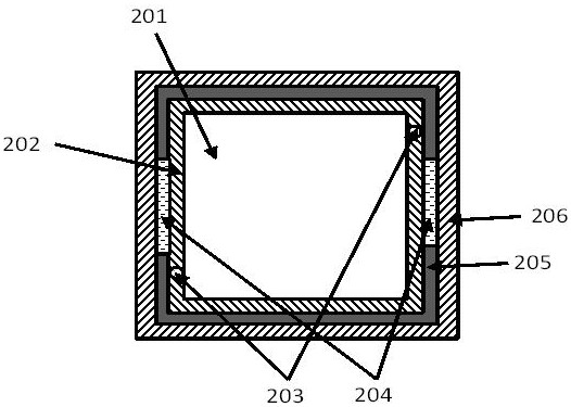
[0055] Such as Figure 1-Figure 6 As shown, this embodiment is based on Embodiment 1, and further includes a temperature control component 104 and a drive controller 105, the liquid crystal polarization modulation component 201 is placed in the temperature control component 104, and the drive controller 105 and the temperature control component 104, Twisted nematic liquid crystal wave plate 101 and antiparallel nematic liquid crystal wave plate 102 are electrically connected:

[0056] The temperature control assembly 104 includes an inner metal frame 202, a temperature detection sensor 203, a semiconductor heating refrigerator 204, a thermal insulation frame 205 and an outer metal frame 206;

[0057] The inner metal frame 202 and the outer metal frame 206 are respectively located at the innermost layer and the outermost layer of the temperature control assembly 104, and the outer metal frame 206 is mounted on the outermost side to realize the packaging of the entire assembly. ...


PUM


Abstract

The invention discloses a novel liquid crystal polarization modulator and a detection method thereof. The novel liquid crystal polarization modulator includes a liquid crystal polarization modulation component, and the liquid crystal polarization modulation component includes a twisted nematic liquid crystal wave plate, an antiparallel nematic liquid crystal wave plate and A linear polarizer, the antiparallel nematic liquid crystal wave plate is arranged between the twisted nematic liquid crystal wave plate and the linear polarizer, the twisted nematic liquid crystal wave plate is located at the front end; the twisted nematic liquid crystal wave plate The alignment directions of the front-end alignment film and the rear-end alignment film of the antiparallel nematic liquid crystal wave plate are all located in the vertical plane of the detection light incident direction; flat. The invention solves the problems of many error sources and low modulation precision in the existing liquid crystal polarization modulation module composed of two nematic liquid crystal adjustable phase retarders and one linear polarizer.

Description

technical field [0001] The invention relates to the technical field of polarization imaging, in particular to a novel liquid crystal polarization modulator and a detection method thereof. Background technique [0002] High-resolution polarization imaging equipment can realize the complementary advantages of polarization imaging technology and light intensity imaging technology, effectively increase the amount of information in optical detection, complete boundary extraction and feature recognition of targets in complex backgrounds, and realize multi-modal information fusion of optical imaging. The "invisible" target becomes "visible" under the ordinary imaging system, which has important application value and broad application prospect in the fields of aerial remote sensing detection, agricultural meteorology and flood emergency monitoring, environmental protection monitoring, criminal evidence identification and target detection. [0003] At present, the commonly used polar...

Claims


Application Information

Patent Timeline
Patent Type & Authority Patents(China)
IPC IPC(8): G01N21/17G01N21/21G01N21/23G01J4/00G02F1/133G02F1/1335G02F1/1337G02F1/1347G02F1/137
CPCG01N21/1717G01N21/17G01N21/21G01N21/23G01J4/00G02F1/13306G02F1/133528G02F1/1337G02F1/1347G02F1/137G01N2021/1725G01N2021/1765G01J4/04
Inventor 王海峰骆永全储松南沈志学曹宁翔温伟峰黄立贤曾建成刘海涛乔冉李大鹏
Owner INST OF FLUID PHYSICS CHINA ACAD OF ENG PHYSICS
Learn More