Slope vibrating separator

A vibrating and separating machine technology, applied in the field of silk reeling machinery, can solve the problem of inconspicuous separation effect, and achieve the effect of simple structure and good separation effect

Inactive Publication Date: 2010-09-22
HANGZHOU TIANFENG TEXTILE MACHINERY
View PDF6 Cites 8 Cited by
  • Summary
  • Abstract
  • Description
  • Claims
  • Application Information

AI Technical Summary

Problems solved by technology

[0003] The present invention provides a slope vibrating separator, which mainly solves the separation mechanism in the prior art, which utilizes the rotation of the wing wheel and the circular grid cylinder in different directions to realize the separation of threadless cocoons and thin-skinned cocoons. Technical issues such as less obvious effects

Method used


Image

  • Slope vibrating separator
  • Slope vibrating separator
  • Slope vibrating separator

Examples


Embodiment

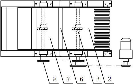
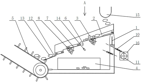
[0017] Embodiment: the slope vibration type separator of this example, as figure 1 , figure 2 , there is a frame 1, the frame is provided with a first vibrating plate 2 and a second vibrating plate 7 inclined downwards in a stepped distribution, the second vibrating plate is located at the lower end of the first vibrating plate, and the first vibrating plate 2 A gap 6 allowing the thin cocoon 14 to fall is left between the second vibrating plate 7 and the length of the gap is 20 mm. Below the first vibrating plate 2 and the second vibrating plate 7, there is a recovery box 4 that can hold thin skin cocoons, and the frame in front of the second vibrating plate is provided with a guide plate 12, and the outlet of the guide plate is provided with a conveying device 5. The frame below the first vibrating plate 2 and the second vibrating plate 7 is respectively provided with a first cam 3 and a second cam 8, and the first cam 3 and the second cam 8 are coaxially connected with a ...


PUM

PropertyMeasurementUnit
lengthaaaaaaaaaa

Abstract

The invention relates to a filature machine, in particular to a slope vibrating separator, which mainly solves the technical problems existing in the prior art that a separation mechanism realizes the separation of cocoons without end and thin shelled cocoons by using a wing wheel and a circular grid stick drum which rotate in different directions, the separation effect is not obvious and the like. The slope vibrating separator comprises a frame (1) and is characterized in that a downward inclined first vibrating plate (2) is arranged on the frame (1), a first cam (3) is arranged on the frame below the first vibrating plate, the first cam is connected with a driving device, a recycle bin (4) for recycling the thin shelled cocoons is arranged below the first vibrating plate, a delivery device (5) for delivering the cocoons without end is arranged at the front of the first vibrating plate, and a clearance (6) for dropping out the thin shelled cocoons is arranged at the front of the first vibrating plate.

Description

technical field [0001] The invention relates to a silk reeling machine, in particular to a slope vibration separator. Background technique [0002] Generally, when silk is reeled, threadless cocoons and thin-skinned cocoons caught by the catcher fall to the separation mechanism. Chinese patent discloses an automatic cocoon quality testing machine (authorized publication number: CN2861978Y), which includes a frame and main transmission parts, and is also equipped with a soup pot part, a cocoon sending part, a thread connecting wing part, a thread adding execution part, a fineness Control parts, small winding and twisting parts, automatic cocoon feeding parts, catcher parts, threading parts, separator parts and pipeline parts, among which the soup pot part is fixedly installed on the frame, the cocoon feeding part and the thread feeding part The cocoon part is fixed on the soup pot part, the connecting wing part, the thread adding execution part and the fineness control part ...

Claims


Application Information

Patent Timeline
Patent Type & Authority Applications(China)
IPC IPC(8): D01B7/02
Inventor 朱建林俞炳朱宇峰俞江乔朱春阳
Owner HANGZHOU TIANFENG TEXTILE MACHINERY
Why Eureka
Try Eureka