Upper cylinder carrying and load arm for a stretching unit

A drafting device and top roller technology, applied in drafting equipment, textiles and papermaking, spinning machines, etc., can solve the problems of changes in machining accuracy, affecting accuracy, affecting slider accuracy, etc., achieving reliable parallel guidance and simplifying manufacturing. , the effect of small production costs

Active Publication Date: 2013-08-28
SAURER COMPONENTS GMBH
View PDF1 Cites 0 Cited by
  • Summary
  • Abstract
  • Description
  • Claims
  • Application Information

AI Technical Summary

Problems solved by technology

[0003] The disadvantage of this anti-rotational fixing of the slider is that in order to adjust the range of the drafting zone by moving the slider in the bracket, a certain gap must be left between the flat rail and the outer wall of the slider, which may be related to the machining accuracy change
This variable gap directly affects the accuracy of the parallel maintenance of the slider relative to the bracket, and further affects the parallel maintenance accuracy of the top roller on the grip frame in the drafting device relative to the corresponding matching bottom roller
The varying machining accuracy negatively affects parallelism

Method used


Image

  • Upper cylinder carrying and load arm for a stretching unit
  • Upper cylinder carrying and load arm for a stretching unit
  • Upper cylinder carrying and load arm for a stretching unit

Examples


Embodiment Construction

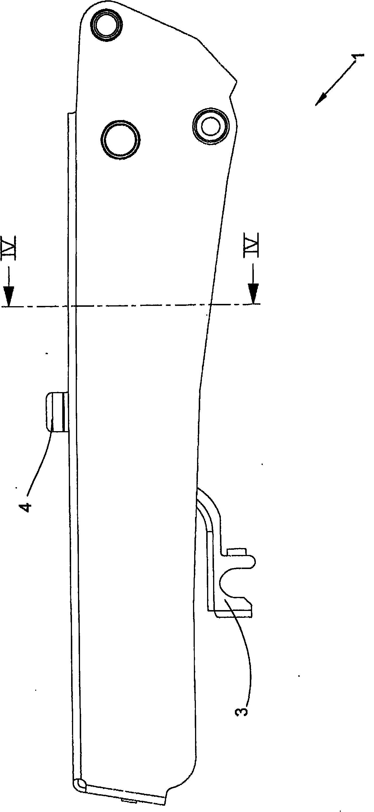
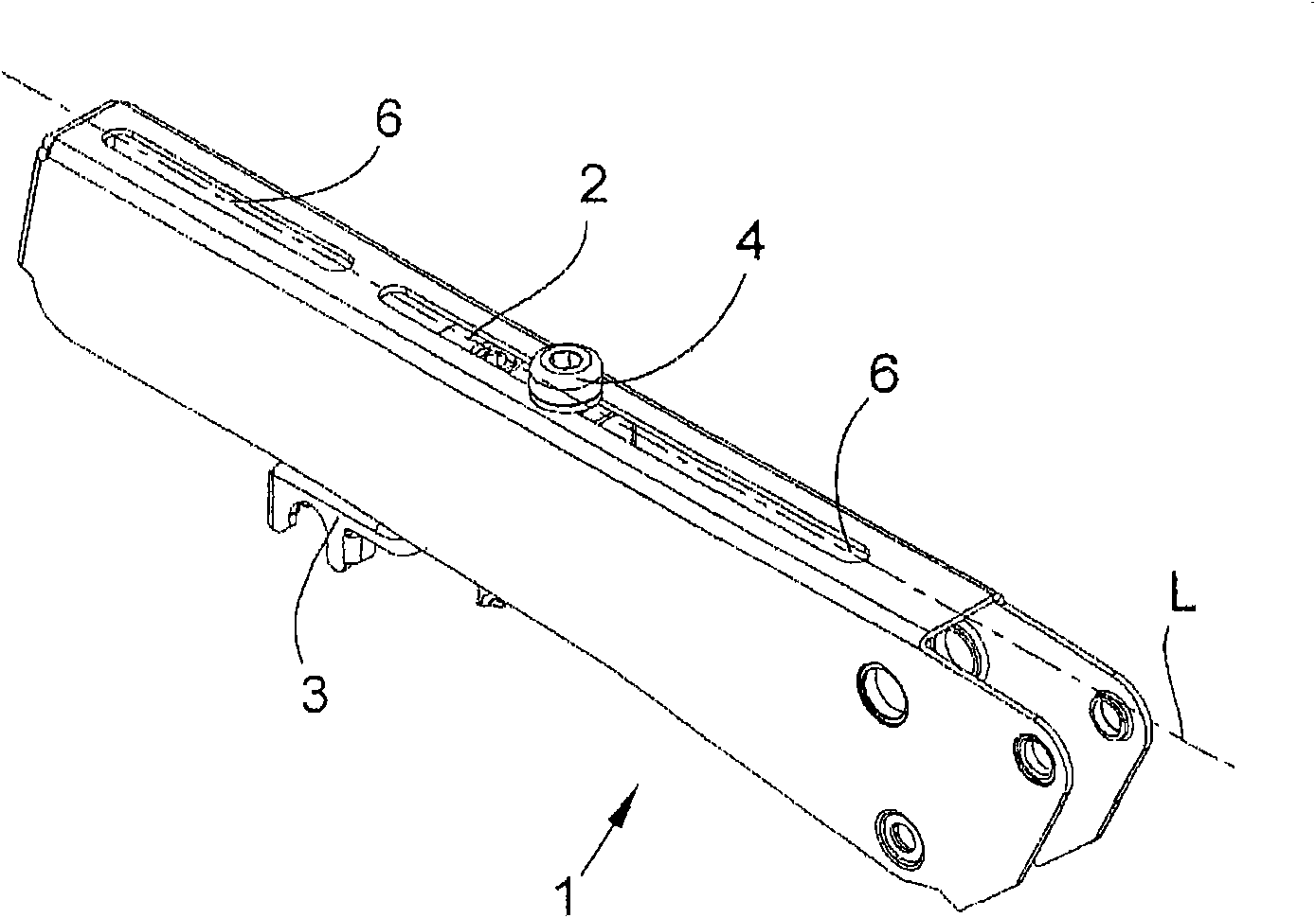
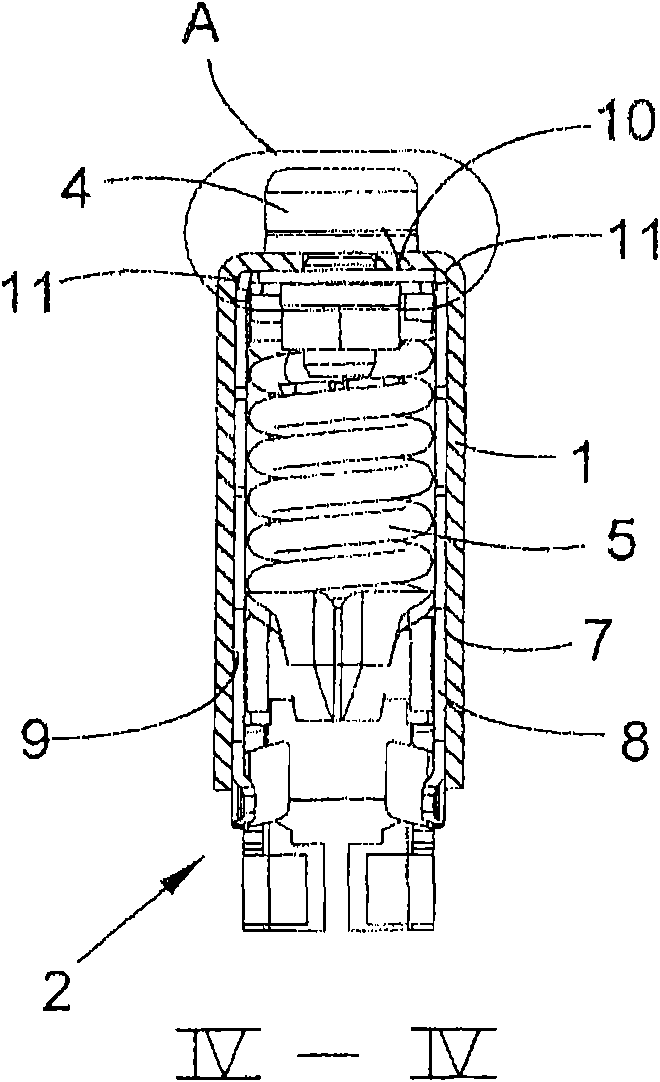
[0038] exist Figure 1 to Figure 6 The view of the drawing shows the bracket 1 for the top roller support and the pressing arm of the drafting device of the spinning frame and at least one preferably U-shaped slider 2 arranged in the bracket 1, the bracket 1 is configured as U-shaped shaped part that opens downwards. The at least one slider 2 is used to accommodate and load the top roller of the drafting device and is fixedly connected to the carriage 1 during the working of the drafting device. It is generally provided that the slide 2 is displaceable along the longitudinal axis L of the carriage 1 in order to adjust the drafting range which is relevant for the function of the drafting device. like figure 2 As shown in the illustration of FIG. 1 , the carriage 1 has on its closed upper side recesses 6 configured as elongated holes, within which recesses 6 the slide 2 can be moved so that the drafting range can be adjusted. The movability and fixability of the slider 2 on ...


PUM


Abstract

The arm has a downwardly open U-shaped carrier (1) in which a U-shaped slide is arranged. The slide includes transitions, sections and a projection on an upper side. The transitions, the sections and the projection cooperate with the carrier in such a manner that the slide is automatically movable against an inner vertical side surface of the carrier during fixation on the slide on an inner horizontal upper side of the carrier by corresponding actuation of an adjusting and fixing device (4). The side surface is adjacent to a peripheral radius.

Description

technical field [0001] The invention relates to a top roller support and a pressing arm used for a drafting device of a spinning frame. The top roller support and a pressing arm have a U-shaped bracket that opens downward, and at least A slider comprising a pressurizing element and a holding frame for receiving the top roller and an adjustment device, by means of which the slider can move longitudinally relative to the carriage and can be fixed on On the bracket, wherein, in order to fix the slider in the U-shaped bracket against rotation about the vertical axis of the slider, the slider uses at least one side wall to cling to the bracket the inner side of the Background technique [0002] German patent DE 39 02 859 A1 discloses a top roller support and pressing arm, which is composed of two flat rails with the same structure, and these two flat rails are arranged on the end side by The spacers are connected to each other and kept parallel to each other. Between the two f...

Claims


Application Information

Patent Timeline
Patent Type & Authority Patents(China)
IPC IPC(8): D01H5/56D01H5/46D01H5/44
CPCD01H5/565
Inventor 约阿希姆·迪德里希
Owner SAURER COMPONENTS GMBH
Why Eureka
Try Eureka