Configuration method for aggregating link service flow and packet switching device

A technology of link aggregation and configuration method, which is applied in the field of communication, can solve problems such as link congestion and bearer load, and achieve the effect of improving efficiency and ensuring service quality

Inactive Publication Date: 2010-09-22
ZTE CORP
View PDF3 Cites 35 Cited by
  • Summary
  • Abstract
  • Description
  • Claims
  • Application Information

AI Technical Summary

Problems solved by technology

However, since this technology is a monitoring mechanism after traffic distribution, the distribution of different service flows on member links is adjusted according to the current actual bandwidth total flow of each port obtained through dynamic monitoring, so the service flow will still be allocated to one When the member link is congested or the bearer load is too large, it will cause repeated adjustments of the service flow to the member link.

Method used


Image

  • Configuration method for aggregating link service flow and packet switching device
  • Configuration method for aggregating link service flow and packet switching device
  • Configuration method for aggregating link service flow and packet switching device

Examples


Embodiment 1

[0072] The implementation example of the present invention describes the link aggregation service flow configuration process when creating a unidirectional LSP passing through an aggregation link.

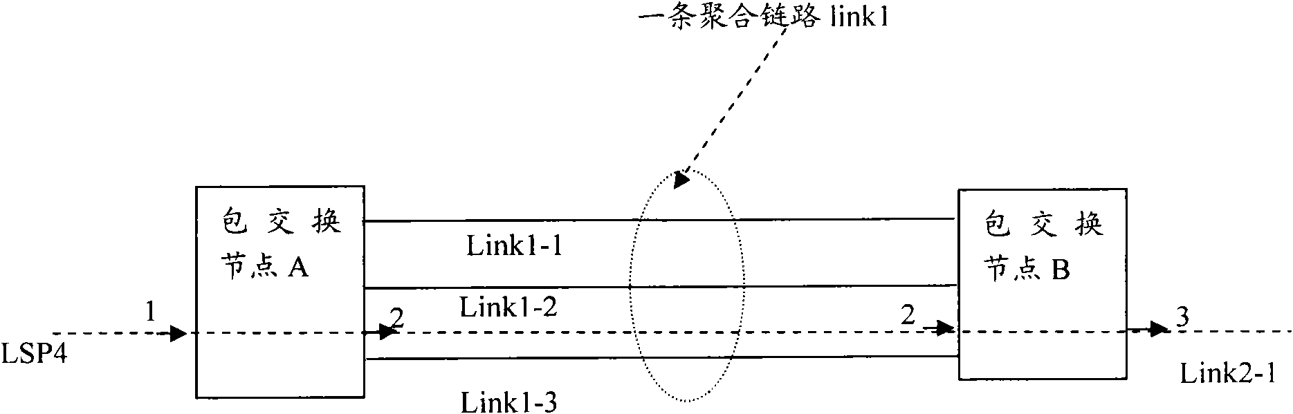
[0073] In this embodiment, the current state information of the aggregated link consists of the following three sets of values:

[0074] 1) LSP1 (9M, Link1-1), LSP2 (9M, Link1-2), LSP3 (3M, Link1-3).

[0075] 2) Member links Link1-1 (20M, 11M), Link1-2 (20M, 11M), and Link1-3 (20M, 17M).

[0076] 3) The aggregate link does not reserve the maximum LSP bandwidth Link1 (17M);

[0077] Since the unreserved bandwidths of Link1-1, Link1-2, and Link1-3 are respectively: 11M, 11M, and 17M, the maximum value of 17M is taken as the unreserved maximum LSP bandwidth of the logical link Link1.

[0078] Among them, LSP4 (its CIR is 11M) is established through distributed RSVP-TE signaling in the network, and LSP4 needs to go through Link1 after route calculation. Figure 4 is a flow chart of ...

Embodiment 2

[0105] In this embodiment, the maintenance of the aggregated links established in the first embodiment is realized. In this embodiment, the initial status information of the aggregated link consists of the following three sets of values:

[0106] 1) Link1-1 (20M, 20M), Link1-2 (20M, 20M), Link1-3 (20M, 0M);

[0107] 2) LSP1 (8M, Link1-3), LSP2 (8M, Link1-3), LSP3 (4M, Link1-3);

[0108] 3) Link1 (20M)

[0109] Figure 5 It is a flow chart of implementing a method for configuring aggregated link service flows in the aggregated link maintenance process according to an embodiment of the present invention. If A receives the aggregated link Link1 resource optimization request from the network management system, then according to Figure 5 As shown, the aggregation link service flow configuration includes the following steps:

[0110] Step S502, during the maintenance process of the aggregated link, according to the need of judgment, reselect the position of the member link wher...


PUM


Abstract

The invention discloses a configuration method for aggregating link service flow and a packet switching device. The method includes: a member link for aggregating link is selected according to bandwidth parameter of service flow; and service flow is carried onto the selected member link. By adopting the invention, the problem that repetitious adjusting from service flow to the member link is caused by jamming of member link or overloading in link aggregation is solved, thus the effects of ensuring service quality of service flow and improving link aggregating efficiency are achieved.

Description

technical field [0001] The present invention relates to the field of communications, in particular to a method for configuring aggregated link service flows and a packet switching device. Background technique [0002] With the growth of data traffic and the improvement of service quality requirements, the provision of high bandwidth has increasingly become the most important feature of packet switching networks, and link aggregation is an important technology to meet the high bandwidth requirements of the network. [0003] The link aggregation technology defined in the IEEE 802.3ad protocol is to combine several physical links between two devices into a logical link (also called an aggregated link), and the link is logically a whole , its internal composition and the details of the transmitted data are transparent to the upper layer services. [0004] In order to realize the balanced load of the data flow in the aggregation link, in the prior art, the Internet Protocol (Int...

Claims


Application Information

Patent Timeline
Patent Type & Authority Applications(China)
IPC IPC(8): H04L12/56H04L29/06H04L47/41
Inventor 杨发明孙德胜柯明陶慕柳向奇敏王福亮
Owner ZTE CORP
Why Eureka
Try Eureka