Surge arrester having a housing and having at least one arresting element

A technology of discharge components and dischargers, applied in electrical components, circuits, spark gap parts, etc., can solve problems such as structure or instrument consumption

Active Publication Date: 2010-09-22
デーンエスエープルスツェオーカーゲー
View PDF4 Cites 7 Cited by
  • Summary
  • Abstract
  • Description
  • Claims
  • Application Information

AI Technical Summary

Problems solved by technology

Conventional separation when heating the varistor and its separation means is not the main purpose in such direct voltage applications, since the system voltage of t...

Method used


Image

  • Surge arrester having a housing and having at least one arresting element
  • Surge arrester having a housing and having at least one arresting element
  • Surge arrester having a housing and having at least one arresting element

Examples


Embodiment Construction

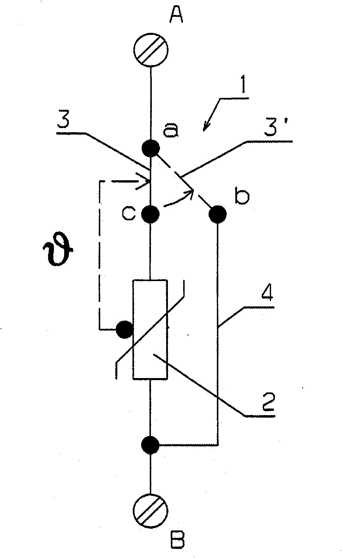
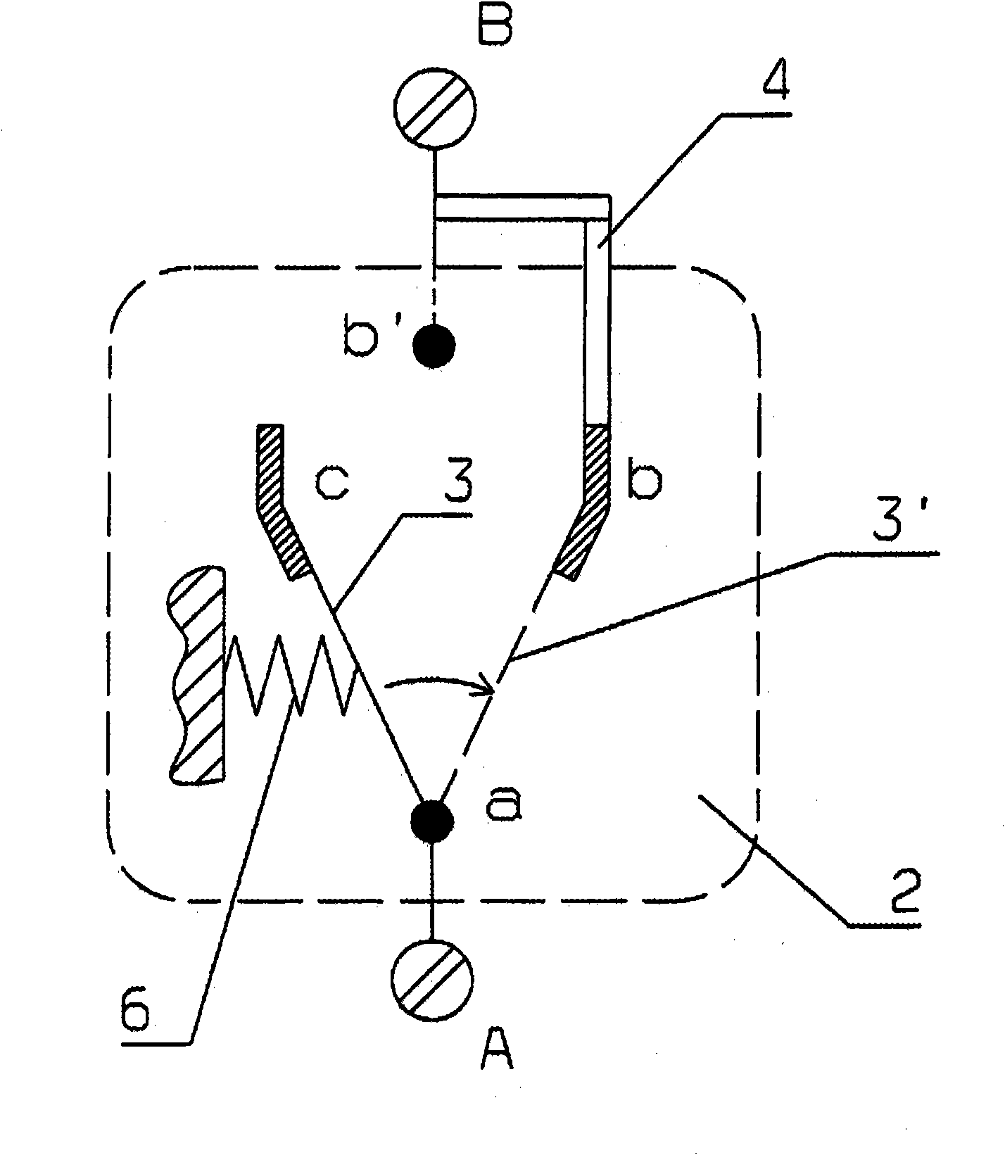
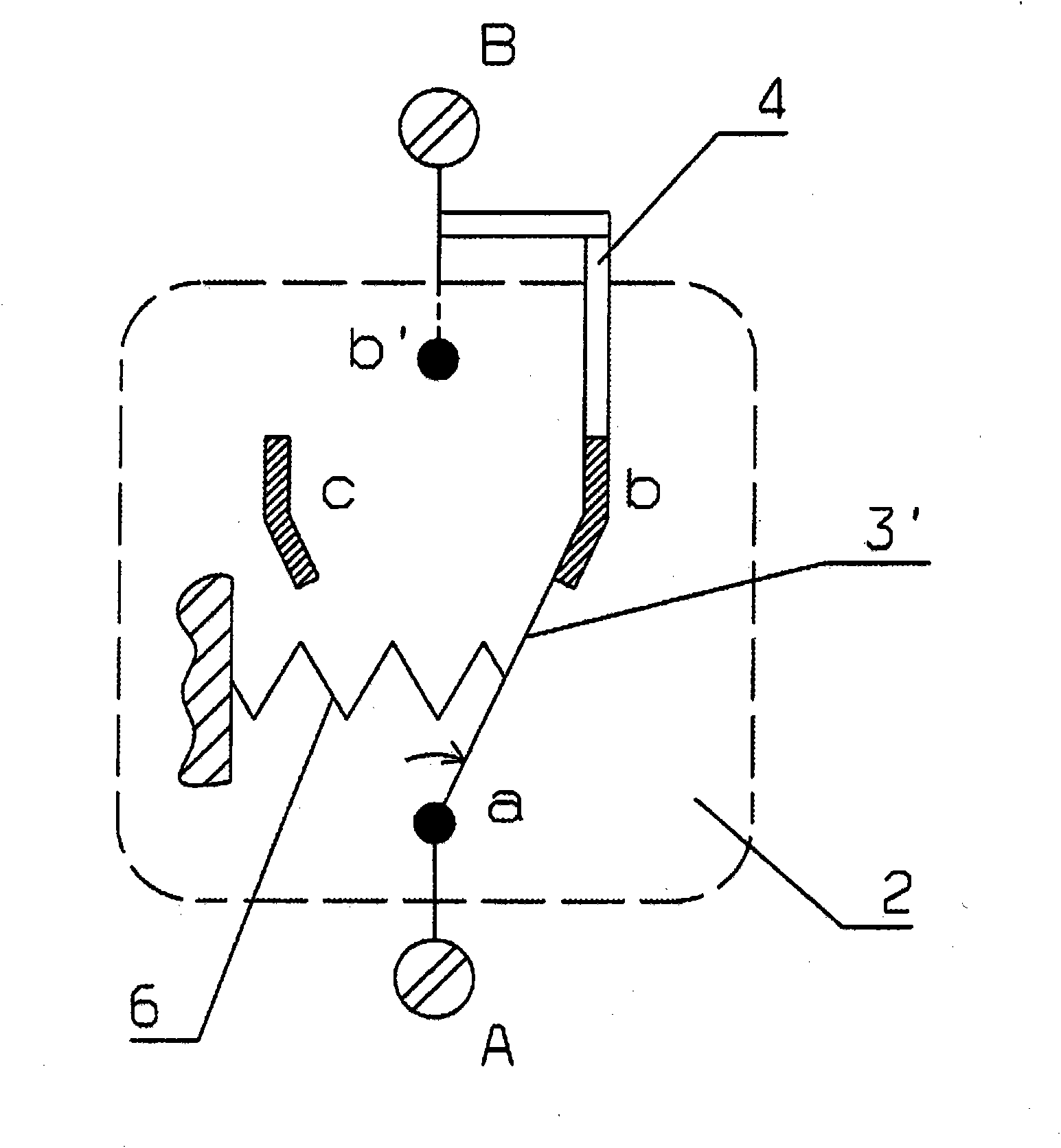
[0036] according to figure 1, connect rheostat 2 between external connections A and B. The varistor 2 can be disconnected via a thermally actuatable disconnecting device (tongue) 3 . There is usually an electrical connection between points a and c via conductor sections or bridges, and in the untriggered state. In state 3' the disconnecting device 1 is triggered and the connection on the path a to b is established by means of the short-circuit bracket 4 which straddles the varistor 2. The operating or triggered short-circuit state is indicated by a dotted line between points a and b. according to figure 2 to 5 after the solder is desoldered in the pressure spring 6 (press Figure 6 and 6b The conversion movement is performed under the influence of the reference number 11).

[0037] figure 2 The switching device 1 with disconnecting and short-circuiting functions is shown schematically in the non-actuated or non-triggered state.

[0038] The short-circuit state of ope...


PUM


Abstract

The invention relates to a surge arrester having a housing (10) and at least one arrester element and a disconnection device, in order to disconnect the arrester element or elements from the mains, the disconnection device comprising a junction (14), which is incorporated in the electrical terminal path (A; B) inside the arrester, a movable conductor section (3) being connected via the junction to the arrester element on the one hand and the conductor section on the other hand, using a first electrical outer terminal of the arrester under over voltage protection, and comprising a means which generates a pre-load force, the force vector in this regard acting indirectly or directly via a movable disconnection bracket (13) on the conductor section or the bridge in the disconnection direction. According to the invention, a conductive element (4; 7) is disposed in the movement path of the conductor section, the first end of the conductive element coming into contact with the conductor section if the disconnection device is triggered, the second end of the element being connected to a second electrical outer terminal, and the conductive element comprising a switching unit or being implemented as a switching unit.

Description

technical field [0001] The invention relates to an overvoltage protection arrester according to the preamble of claim 1 as a supplement to German Patent Application No. 102006052955.3, comprising a housing and at least one discharge element, such as a varistor, and for connecting the discharge element to the grid A separate separating device comprising a soldering point which is connected to the electrical connection path inside the arrester, on the one hand the movable conductor section or the movable conductive bridge is connected via the soldering point to the The discharge element is connected, and the conductor section or bridge is connected to the electrical first external connection of the discharger on the other hand, and comprises a component that generates a pretension force, such as a spring, the force vector associated therewith indirectly or directly via the movable separating The support acts on the conductor sections or bridges in the direction of separation. ...

Claims


Application Information

Patent Timeline
IPC IPC(8): H01T1/14
CPCH01T1/14
Inventor J·埃尔勒A·埃尔哈特S·施莱特
Owner デーンエスエープルスツェオーカーゲー
Why Eureka
Try Eureka