Close-fitting combined structure of cooling fin and heat pipe of radiator

A combined structure and heat sink technology, applied in heat exchange equipment and other directions, can solve the problems of increased liquid flow resistance and other issues

Active Publication Date: 2010-09-29
DONG GUAN HAN XU HARDWARE & PLASTIC TECH CO LTD
View PDF6 Cites 7 Cited by
  • Summary
  • Abstract
  • Description
  • Claims
  • Application Information

AI Technical Summary

Problems solved by technology

[0003] Known about the combination technology of heat sink and heat pipe, some people also set through holes on the surface of heat sink and through grooves connecting the through holes, use the molded parts with continuous concave and convex punches at the head end to penetrate through the grooves, and then punch and form to compress the heat pipes The concave part tightly connected with the through hole achieves the eff

Method used


Image

  • Close-fitting combined structure of cooling fin and heat pipe of radiator
  • Close-fitting combined structure of cooling fin and heat pipe of radiator
  • Close-fitting combined structure of cooling fin and heat pipe of radiator

Examples


Embodiment Construction

[0040] The invention will be further described below in conjunction with the accompanying drawings and specific embodiments.

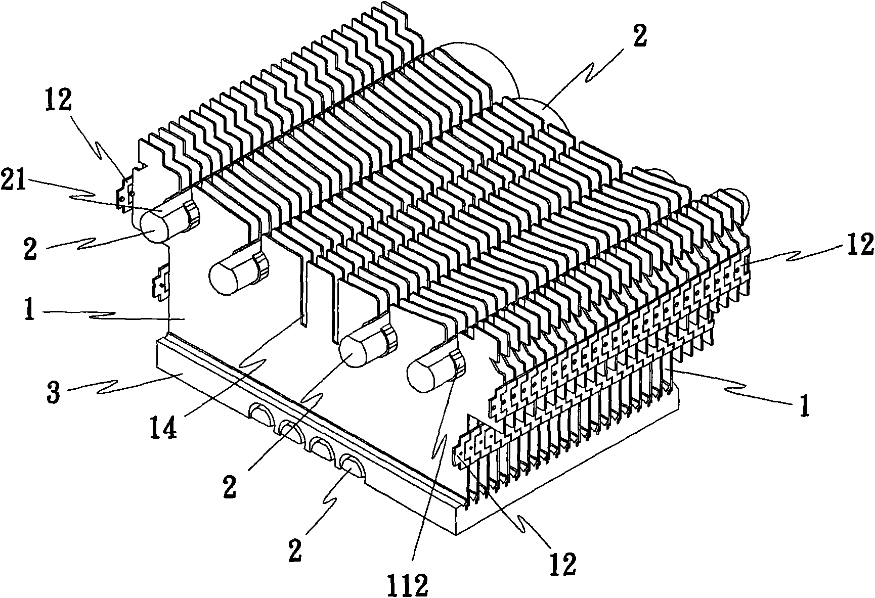
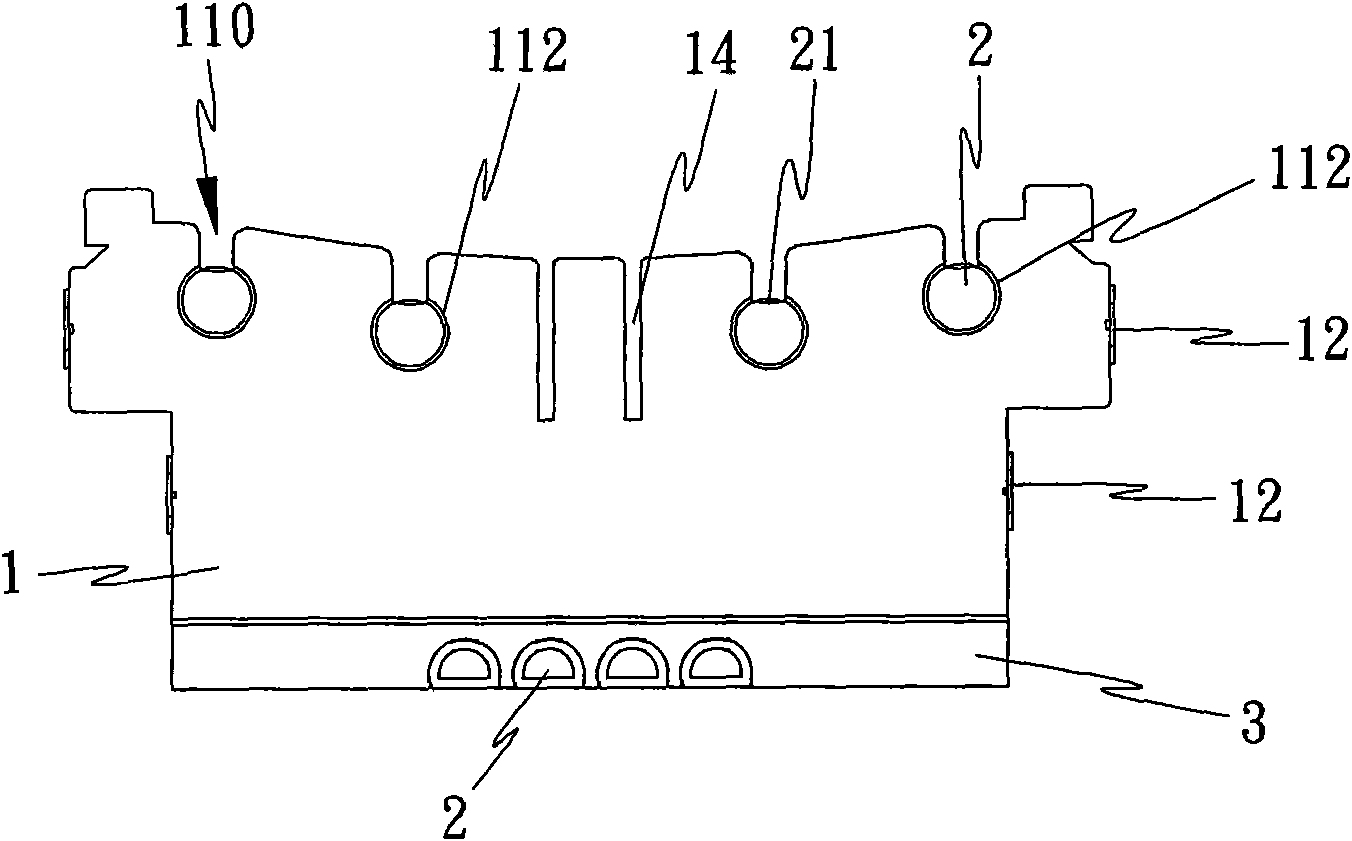
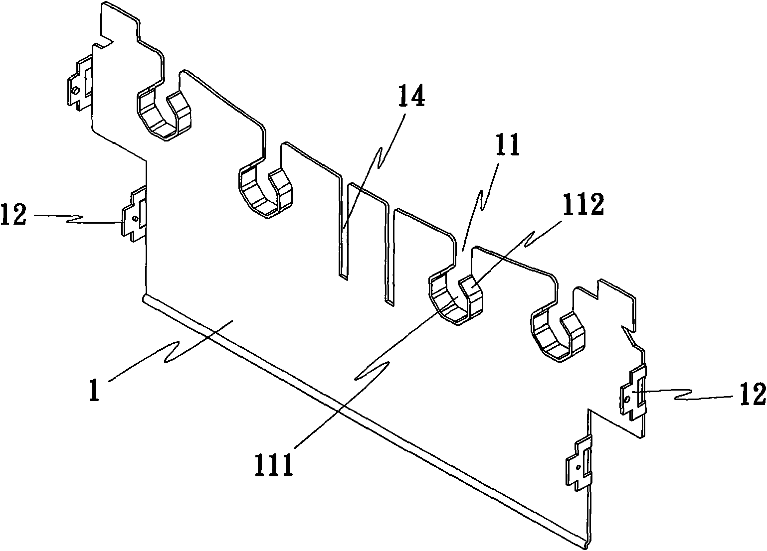
[0041] Such as Figure 1 to Figure 5 As shown, the present invention is a tight-fit combination structure of radiator fins and heat pipes, including a plurality of heat sinks 1, more than one heat pipe 2 and a base 3, wherein:

[0042] A plurality of heat sinks 1, such as image 3 , Figure 4 As shown, the upper end surface of each heat sink 1 is provided with more than one concave hole groove 11, and the bottom of the concave hole groove 11 all extends to form a special-shaped hole 111 different from the shape of the heat pipe body (such as an octagonal hole as shown in the figure, or various polygonal holes, or other regular or irregular almost-shaped holes), and a plurality of adjacent concave holes are used in series to form a long groove 110 that allows the stamping die 4 to pass through (Such as Figure 5 , Figure 7 ).

[0043] More than o...


PUM


Abstract

The invention relates to a close-fitting combined structure of cooling fins and heat pipes of a radiator, comprising a plurality of cooling fins, more than one heat pipe and a base, wherein each cooling fin is combined on the base, and the heat pipes respectively passes thorough and are embedded in the cooling fins and the base. The close-fitting combined structure is characterized in that the upper end surface of each cooling fin is provided with more than one concave hole groove; the bottom of the concave hole groove forms one profile hole with a shape different from the shape of the pipe body of the heat pipe; the plurality of adjacent concave hole grooves are connected in series to form a long trough allowing a stamping die to pass; the heat pipe correspondingly is arranged at the bottom of the concave hole groove to match with a jig and a stamping module to pass through the long trough; stamping is carried out by aiming at the pipe body of the heat pipe so that the pipe body of the heat pipe is matched and extruded by the profile hole and then is relatively deformed to produce profile side wall shape, and the cooling fin and the heat pipe are tightly matched and assembled.

Description

technical field [0001] The invention relates to a tightly matched combined structure of heat sink fins and heat pipes, which mainly uses the special-shaped holes (such as polygonal holes) of the heat sink to cooperate with stamping dies to stamp the heat pipe body, so that the heat pipe body is subjected to the matching pressure of the special-shaped holes. Squeeze, the relative deformation produces a special-shaped side wall shape, so that the heat sink and the heat pipe are in a tight fit. Background technique [0002] The main components of conventional heat sinks include heat sinks, heat pipes, and bases. For the combination of heat sinks and heat pipes, the most common method is welding, which uses electroplating, solder paste or adhesives and other manufacturing processes or processing media. However, the heat sink and the heat pipe are welded and combined, but it does not meet the environmental protection requirements. [0003] Known about the combination technology ...

Claims


Application Information

Patent Timeline
IPC IPC(8): B21D53/08
Inventor 黄崇贤
Owner DONG GUAN HAN XU HARDWARE & PLASTIC TECH CO LTD
Why Eureka
Try Eureka