Micro lens and micro lens array

A micro-lens array and micro-lens technology, applied in the field of micro-lenses, can solve problems such as glare or ghosting, image sensor reception, and whitening of photos, and achieve the effect of solving glare and ghosting

Inactive Publication Date: 2010-09-29
HONG FU JIN PRECISION IND (SHENZHEN) CO LTD +1
View PDF7 Cites 10 Cited by
  • Summary
  • Abstract
  • Description
  • Claims
  • Application Information

AI Technical Summary

Problems solved by technology

[0003] Because the current manufacturing process is immature, the microlenses that have been used still have many deficiencies, especially the images formed by some microlenses appear to be white and haloed, mainly because the surface of the lens will reflect a part of the incident light. Light, the reflected light of each lens is reflected multiple times inside the lens and camera to become stray light, which makes the image sensor receive unnecessary light signals, resulting in the above problems, generally known as glare or ghost

Method used


Image

  • Micro lens and micro lens array
  • Micro lens and micro lens array
  • Micro lens and micro lens array

Examples


Embodiment Construction

[0017] The present invention will be described in further detail below in conjunction with the accompanying drawings.

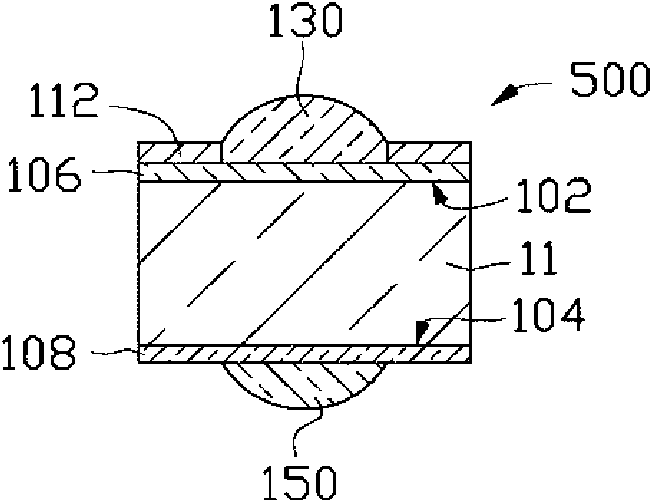
[0018] see figure 1 The microlens 500 provided by the embodiment of the present invention includes a light-transmitting substrate 11 , a first optical part 130 , a second optical part 150 , an anti-reflection layer 106 surrounding the first optical part 130 , a matting film 112 , and a filter layer 108 .

[0019] The light-transmitting substrate 11 has a first surface 102 and a second surface 104 opposite to each other. An anti-reflection layer 106 is disposed on the first surface 102 . The first optical part 130 and the matting film 112 are disposed on the anti-reflection layer 106 . The matting film 112 is disposed around the first optical portion 130 .

[0020] The filter layer 108 is disposed on the second surface 104 , and the second optical portion 150 is disposed on the filter layer 108 .

[0021] Both the first optical part 130 and the second optica...


PUM


Abstract

The invention provides a micro lens which comprises a transparent base plate, a first antireflection layer, a first optical part anda first extinction film, wherein the transparent base plate is provided with a first surface and a second surface opposite to the first surface; the first antireflection layer is arranged on the first surface; the first optical part is arranged on the first antireflection layer; and the first matt film is arranged on the first antireflection layer and surrounds the first optical part. The invention also provides a micro lens array which can be cut into a plurality of the micro lenses. The micro lens is provided with the matt film and the antireflection layer, thereby being capable of preventing the micro lens from generating glare and ghost images in the imaging process.

Description

technical field [0001] The invention relates to the field of optical components, in particular to microlenses for miniaturized electronic equipment. Background technique [0002] In view of the fact that portable and lightweight portable electronic devices are increasingly favored by consumers, research on the miniaturization of various components has become a research hotspot for researchers, and microlenses are one of them. A microlens is an extremely small lens that can be used in optoelectronic components such as digital cameras, mobile phones or solar cells. [0003] Due to the immature manufacturing process at present, the microlenses that have been used still have many shortcomings, especially the images formed by some microlenses appear to be white and haloed, mainly because the surface of the lens will reflect a part of the incident light. Light, the light reflected by each lens is reflected multiple times inside the lens and camera to become stray light, which cau...

Claims


Application Information

Patent Timeline
Patent Type & Authority Applications(China)
IPC IPC(8): G02B3/00G02B1/11
CPCG02B1/11G02B3/0031G02B27/0018G02B3/0062
Inventor 余泰成
Owner HONG FU JIN PRECISION IND (SHENZHEN) CO LTD
Why Eureka
Try Eureka