
Manufacturing method of multi-pipe tubular joint

A technology of intersecting nodes and production methods, applied in the direction of buildings and building structures, can solve the problems of increased cost input, complex stress distribution, difficulty in ensuring uniformity, etc., and achieve the effect of ensuring bearing capacity and ensuring accuracy

Inactive Publication Date: 2010-10-06
CHINA CONSTR STEEL STRUCTURE CORP LTD
View PDF0 Cites 27 Cited by
  • Summary
  • Abstract
  • Description
  • Claims
  • Application Information

AI Technical Summary

Problems solved by technology

[0003] Among the existing intersecting nodes, there is a kind of multi-branched multi-pipe intersecting node. This kind of intersecting node has many branches, all of which are located in space, and its stress distribution is relatively complicated. The existing manufacturing process cannot guarantee the The precise positioning and assembly of each branch of the intersecting joint cannot guarantee the bearing capacity of the multi-pipe intersecting joint. Therefore, the existing application projects for multi-pipe intersecting joints mostly use cast steel joints instead; and cast steel joints not only Increased cost input cannot reflect the economy of the original design node form (multi-pipe intersecting nodes); and the casting quality of large and complex cast steel nodes is difficult to guarantee
The material of complex cast steel joints is difficult to ensure uniformity, and microscopic defects are prone to occur; the material of cast steel joints is often different from that of the rods to be connected, which increases the risk of welding quality under poor construction conditions on site

Method used


Image

  • Manufacturing method of multi-pipe tubular joint
  • Manufacturing method of multi-pipe tubular joint
  • Manufacturing method of multi-pipe tubular joint

Examples


Embodiment

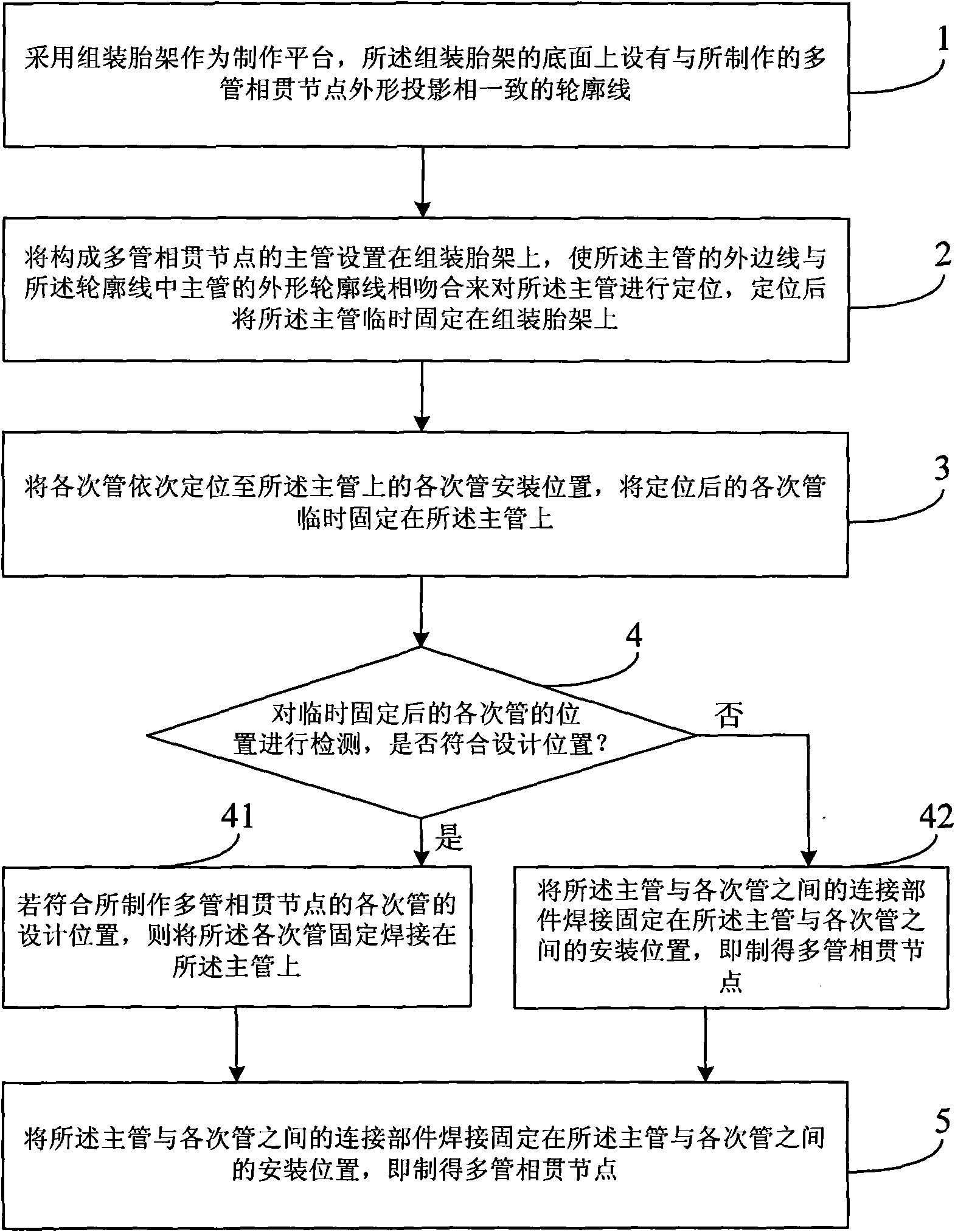
[0036] This embodiment provides a method for manufacturing multi-pipe intersecting nodes, which can manufacture multi-pipe intersecting nodes that meet the requirements in precision and bearing capacity, and solve the problem that the existing technology cannot guarantee the accuracy and accuracy of multi-pipe intersecting nodes. Bearing capacity, but in steel structure engineering, cast steel joints are used to replace multi-pipe intersecting joints, resulting in high cost and low engineering quality; for example figure 1 As shown, the manufacturing method of the multi-pipe intersecting node includes the following steps:

[0037] Step 1, using the assembled tire frame as a production platform, the bottom surface of the assembled tire frame is provided with contour lines consistent with the shape projection of the fabricated multi-pipe intersecting nodes;

[0038] In the above step 1, on the bottom surface of the assembled tire frame, there is a contour line consistent with th...


PUM


Abstract

The invention discloses a manufacturing method of a multi-pipe tubular joint, which comprises the following steps of: arranging a contour line which is consistent with the projection of the profile of a multi-pipe tubular joint to be manufactured on the bottom surface of an assembly jig as a manufacturing platform; arranging a mine pipe for the multi-pipe tubular joint on the assembly jig, enabling the outer side lines of the primary pipe to be matched with the profile contour line of the primary pipe in the contour line to locate the primary pipe, and then temporarily fixing the primary pipe on the assembly jig; sequentially locating secondary pipes in secondary pipe installation positions on the primary pipe, and then temporarily fixing the located secondary pipes on the primary pipe; detecting the positions of the temporarily fixed secondary pipes; in case of conforming to the design positions of the secondary pipes of the multi-pipe tubular joint, welding the secondary fixed pipes on the primary pipe; and fixedly welding connecting parts between the primary pipe and secondary pipes in the in the installation positions between the primary pipe and the secondary pipes, thereby obtaining the multi-pipe tubular joint. Thus, the method realizes the manufacturing of the high-precision multi-pipe tubular joint in a simple mode.

Description

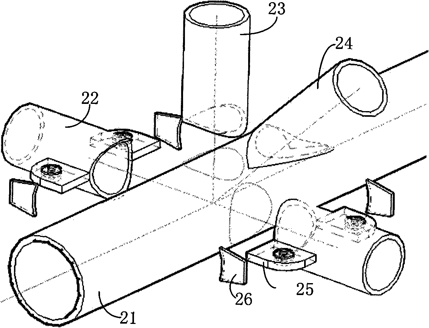
technical field [0001] The invention relates to the field of building construction, in particular to a method for manufacturing a multi-pipe intersecting node. Background technique [0002] Intersecting joints are often used in steel structure engineering, which is a three-dimensional space structure formed by the intersection of multiple bars. Among the multiple intersecting rods, the main rod with thicker wall thickness and higher rigidity runs through, and the remaining secondary rods are directly welded to the outer surface of the main rod after being processed by intersecting lines. Because of its simple and clear appearance, no need to add joint components (such as welding balls, bolt balls, etc.), it has the characteristics of low cost and reasonable joint structure, and has become an ideal joint form in steel structure engineering. It has been successfully used in many domestic steel structure projects, such as Guangzhou Stadium, Capital Airport New Terminal, Shenzh...

Claims


Application Information

Patent Timeline
IPC IPC(8): E04B1/58E04B1/24
Inventor 王宏张琨戴立先刘曙周发榜刘家华朱永清蒋官业段其磊
Owner CHINA CONSTR STEEL STRUCTURE CORP LTD
Learn More