Pipeline connection structure of heat exchanger

A connection structure, heat exchanger technology, applied in heat exchange equipment, adjustable connections, heat exchanger shells, etc., can solve the problems of difficult on-site maintenance, leakage at welding, high working intensity, etc., and avoid the easy vibration of welding joints. damage, eliminating the welding process, reducing the effect of management costs

Inactive Publication Date: 2010-10-06
谭仲禧
View PDF11 Cites 1 Cited by
  • Summary
  • Abstract
  • Description
  • Claims
  • Application Information

AI Technical Summary

Problems solved by technology

However, welding is carried out at high temperature, and irritating gas is generated at the same time, which affects the environment, and the work intensity is high. The pipes are fixedly connected. The fi

Method used


Image

  • Pipeline connection structure of heat exchanger
  • Pipeline connection structure of heat exchanger
  • Pipeline connection structure of heat exchanger

Examples


Embodiment 1

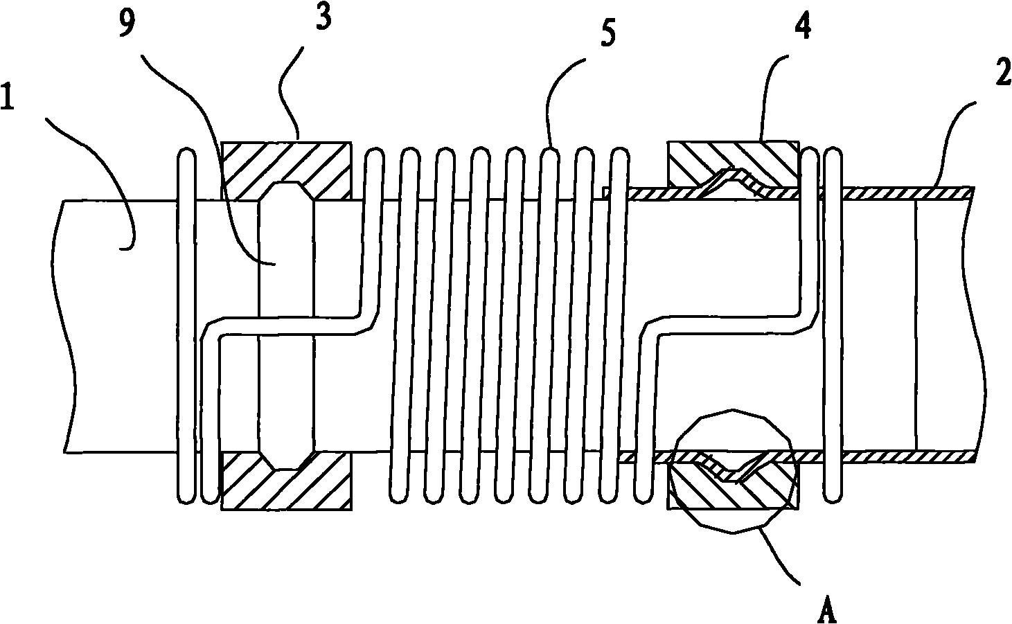
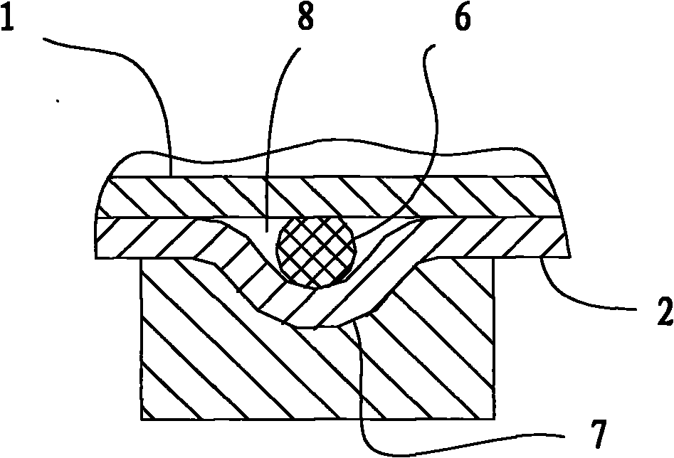
[0027] refer to figure 1 with 2 , a pipe connection structure of a heat exchanger, which includes a connecting pipe 1, a heat dissipation straight pipe 2, a first positioning block 3, a second positioning block 4 and an elastic member 5, wherein the end of the connecting pipe 1 is inserted into the heat dissipation straight pipe In the end of the tube 2, a protrusion 7 with an annular groove 8 is provided on the tube wall of the heat dissipation straight tube 2 at the insertion point, the sealing ring 6 is arranged in the annular groove 8, and the first positioning block 3 is fixed on the connecting tube 1 Above, the second positioning block 4 is fixed on the heat dissipation straight pipe 2, and the two ends of the elastic member 5 are connected to the first positioning block 3 and the second positioning block 4 respectively.

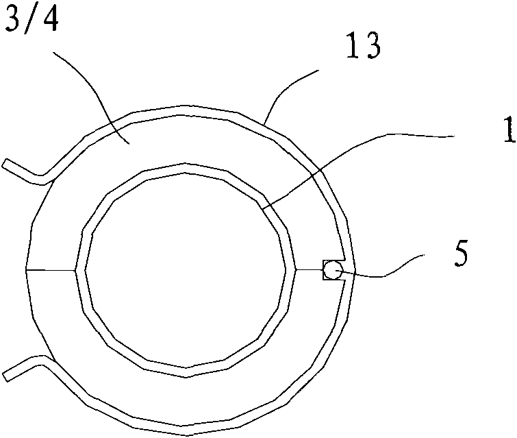
[0028] refer to image 3 , Ring clamps 13 are sheathed outside the first positioning block 3 and the second positioning block 4 respectively.

[00...

Embodiment 2

[0034] refer to Figure 8 with 9 , a pipe connection structure of a heat exchanger, which differs from Embodiment 1 in that: the connection pipe 1 is a U-shaped pipe, and its two ends are respectively inserted into two heat dissipation straight pipes 2, and the second positioning block 4 The two ends are respectively fixed behind the protrusions 7 of the two heat dissipation straight pipes 2 , and the middle part of the connecting pipe 1 is provided with a circular ring 9 .

[0035] Installation of Embodiment 2 of the present invention: Set sealing rings 6 in the protrusions 7 of the two heat dissipation straight pipes 2 respectively, then insert the two ends of the connecting pipe 1 into the ends of the two heat dissipation straight pipes 2 respectively, and install the second The first positioning block 3 and the second positioning block 4 are provided with an elastic member 5 to realize the connection of the pipelines.

[0036] When the pressure of the heat exchange mediu...

Embodiment 3

[0038] refer to Figure 10 with 11 , a pipe connection structure of a heat exchanger, which is different from Embodiment 2 in that: the connection pipe 1 is a U-shaped pipe, and its two ends are respectively inserted outside the ends of two heat dissipation straight pipes 2. A ring protrusion 15 with a ring groove 16 is provided on the pipe wall of the connecting pipe 1 at the location, and the sealing ring 6 is arranged in the ring groove 16 .


PUM


Abstract

The invention discloses a pipeline connection structure of a heat exchanger, comprising a connecting tube, a heat-radiating straight tube, a first locating block, a second locating block and an elastic piece, wherein the connecting tube and the heat-radiating straight tube are sheathed, spliced and connected by an end part; a seal ring is arranged between the walls of the heat-radiating straight tube and the connecting tube at the splicing position; the first locating block is fixed on the outer wall of the connecting tube, the second locating block is fixed on the outer wall of the heat-radiating straight tube, and two ends of the elastic piece are respectively connected with the first locating block and the second locating block. The invention has the advantage that installation and arrangement are convenient, the working procedure of welding omitted, parts and components transportation of large rack tubes can be realized and installation on the spot is simple so that the phenomenon that welded junctions are easy to be damaged due to the transportation, and at the same time, the structure of the sealed rack tube is changed along with the variation of the volume of medium in the tube under the sealing without breaking and the management cost of the heat exchanger in the operation is lowered.

Description

technical field [0001] The invention relates to a pipeline connection structure, in particular to a pipeline connection structure for liquid transmission. Background technique [0002] In the existing tube heat exchanger, the heat exchange medium flows in the tube and exchanges heat with the air or liquid outside the tube through the tube wall. In order to increase the heat exchange area per unit volume of the heat exchanger, the heat exchange tubes are usually arranged in a manner of distributing a plurality of straight tubes on several planes. This produces the problem of connecting between straight pipes and straight pipes and between straight pipes and curved pipes. The usual way is to use welding to connect. However, welding is carried out at high temperature, and irritating gas is generated at the same time, which affects the environment, and the work intensity is high. The pipes are fixedly connected. The finished product is large in size and inconvenient to transpor...

Claims


Application Information

Patent Timeline
IPC IPC(8): F28F9/26
CPCF16L27/12F16L51/00F28F9/26
Inventor 谭仲禧
Owner 谭仲禧
Why Eureka
Try Eureka