Method for measuring deep rock-sample initial damage distribution

A technology of initial damage and measurement method, which is applied in material analysis using sonic emission technology, solid analysis using sonic/ultrasonic/infrasonic waves, and testing of material strength by applying repetitive force/pulse force, etc. Serious problems, to achieve the effect of ensuring rationality

Active Publication Date: 2010-10-06
POWERCHINA HUADONG ENG COPORATION LTD
View PDF4 Cites 35 Cited by
  • Summary
  • Abstract
  • Description
  • Claims
  • Application Information

AI Technical Summary

Problems solved by technology

[0002] The construction of deep burial projects requires rock sampling under deep burial conditions. The commonly used sampling methods include drilling sampling (core samples) and rock sampling (on-site rock blocks

Method used


Image

  • Method for measuring deep rock-sample initial damage distribution
  • Method for measuring deep rock-sample initial damage distribution
  • Method for measuring deep rock-sample initial damage distribution

Examples


Embodiment 1

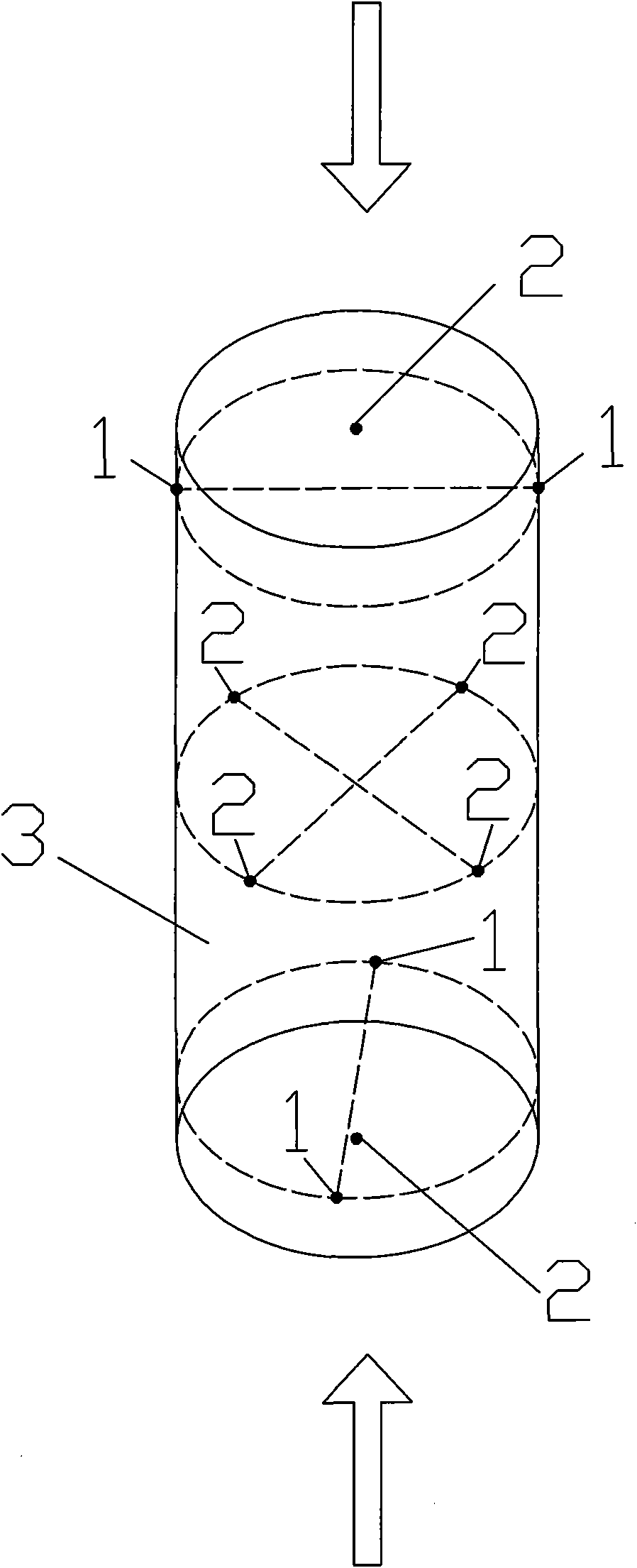
[0017] Such as figure 1 As shown, in this example, the distribution of the initial damage of deep rock samples is determined, and the specific steps are as follows:

[0018] a. Process rock sample 3. In order to more accurately test the distribution of initial damage in the rock sample and to facilitate the arrangement of acoustic waves and acoustic emission probes, a cylindrical rock sample with a diameter of 80-100 mm is generally selected. The diameter of the rock sample used in this example is 80 mm , Aspect ratio of 2:1 (160mm high).

[0019] b. Grind a small platform at the position where the probe is to be placed on the rock sample to ensure that the probe and the rock sample are fully coupled (the acoustic wave detection probe 2 and the acoustic emission probe 1 selected in this example are both flat-bottomed probes). Arrange a pair of acoustic detection probes 2 on the top and bottom of the rock sample (this pair of probes should be coupled with the indenter of the t...

Embodiment 2

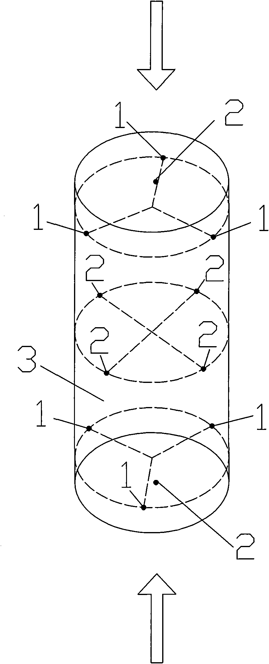
[0025] Such as figure 2 As shown, in this example, the distribution of the initial damage of deep rock samples is determined, and the specific steps are as follows:

[0026] a. To process rock sample 3, select a cylindrical rock sample with a height of 200 mm and a diameter of 100 mm.

[0027] b. Grind a small platform at the position where the probe is to be placed on the rock sample to ensure that the probe and the rock sample are fully coupled (the acoustic wave detection probe 2 and the acoustic emission probe 1 selected in this example are flat-bottomed probes). Arrange a pair of acoustic wave detection probes 2 on the top and bottom of the rock sample, and arrange two pairs of acoustic wave detection probes 2 at the two ends of the two diameters perpendicular to each other in the axial middle of the rock sample. Each pair of acoustic wave detection probes includes a transmitting probe and a Receive probe.

[0028] c. Arrange a group of acoustic emission probes 1 near ...


PUM

PropertyMeasurementUnit
Diameteraaaaaaaaaa
Diameteraaaaaaaaaa

Abstract

The invention relates to a method for measuring deep rock-sample initial damage distribution, aiming to provide a simple and feasible method for measuring deep rock-sample initial damage distribution, which can obtain the initial damage distribution situation of a rock sample and further reasonably determine loading mode and loading direction of the rock sample. The method comprises the following steps: processing the rock sample; installing an acoustic detection probe and an acoustic emission probe; carrying out a uniaxial loading test on the rock sample; determining the crack initiating strength of the rock sample; and carrying out comprehensive analysis on three-way acoustic wave velocity and distribution of acoustic emission events of the rock sample, and finally determining initial damage distribution of the rock sample. The method is applicable to a rock mechanical test which serves underground engineering such as deeply-buried hydraulic and hydro-power engineering, traffic, mine and the like.

Description

technical field [0001] The invention relates to a method for measuring the initial damage distribution of deep rock samples, in particular to a method for measuring the initial damage distribution of deep rock samples caused by stress relief during the sampling process. It can be used for rock mechanics tests for deep buried water conservancy and hydropower projects, transportation, mines and other underground projects. Background technique [0002] The construction of deep burial projects requires rock sampling under deep burial conditions. The commonly used sampling methods include drilling sampling (core samples) and rock sampling (on-site rock blocks). These two sampling methods are relatively difficult under deep burial conditions. Severe core sample damage, and the degree of damage becomes more serious with the increase of buried depth and the increase of ground stress level. Therefore, when using these deep rock samples for rock mechanics laboratory tests, in order t...

Claims


Application Information

Patent Timeline
IPC IPC(8): G01N3/32G01N29/14G01N29/07
Inventor 严鹏单治钢陈祥荣张春生陈永红
Owner POWERCHINA HUADONG ENG COPORATION LTD
Why Eureka
Try Eureka