
Micro-projector

A projection and microlens array technology, applied in the field of projection display systems, can solve the problems of limited mobility, large volume, and difficult manipulation.

Inactive Publication Date: 2010-10-06
EXPLAY
View PDF5 Cites 51 Cited by
  • Summary
  • Abstract
  • Description
  • Claims
  • Application Information

AI Technical Summary

Problems solved by technology

As a result, projector systems based solely on high powered lamps or other incoherent sources are very large, difficult to maneuver, have limited mobility, and therefore cannot be scaled down to very compact portable handheld projection devices

Method used


Image

  • Micro-projector
  • Micro-projector
  • Micro-projector

Examples


Embodiment Construction

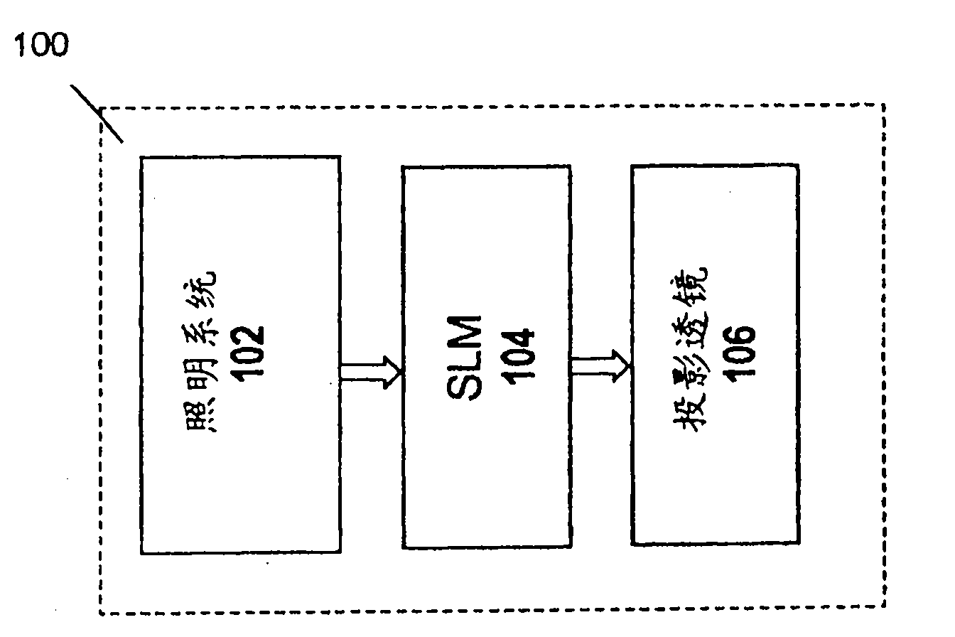
[0062] refer to Figure 1A , Figure 1A A schematic representation of an example of a compact projection display 100 of the present invention is shown. The projection display includes: an illumination system 102 for generating one or more light beams, such as multiple light beams of different wavelengths, typically primary colors (RGB) or YRGB or a broader set of colors; a spatial light modulator (SLM) system 104 , which may be configured as an LCD, T-LCOS, LCOS or DMD panel; and projection optics, typically a lens unit 106 . It should be noted that the projection display may comprise a separate SLM for each light illumination channel or a common SLM for at least two channels.

[0063] For ease of understanding, the same reference numerals are used to identify some components that are common in all examples.

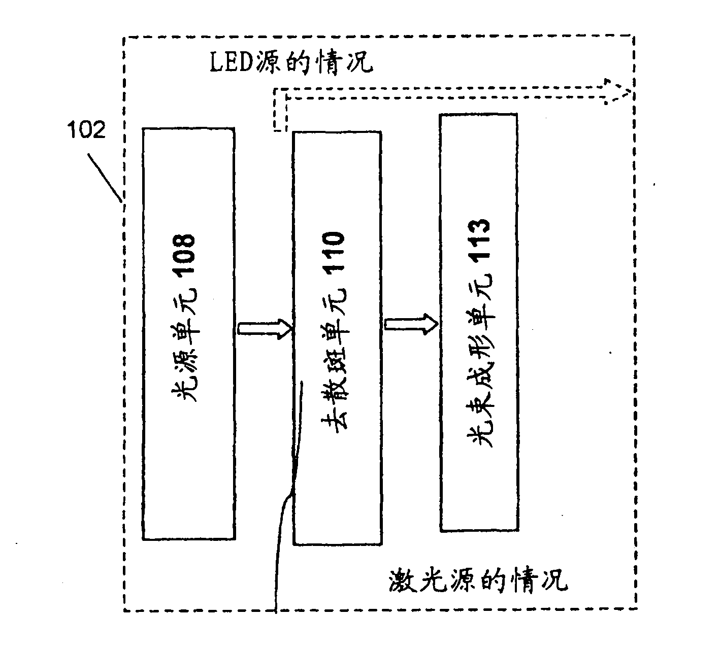
[0064] refer to Figure 1B , Figure 1B A block diagram of an illumination system 102 is shown comprising: a light source unit 108 having, in this example, a pluralit...


PUM


Abstract

The present invention provides a projection display comprising an illumination system comprising at least one laser source unit and configured and operable for producing one or more light beams; a spatial light modulating (SLM) system accommodated at output of the illumination system and comprising one or more SLM units for modulating light incident thereon in accordance with image data; and a light projection optics for imaging modulated light onto a projection surface. The illumination system comprises at least one beam shaping unit comprising a Dual Micro-lens Array (DMLA) arrangement formed by front and rear micro-lens arrays (MLA) located in front and rear parallel planes spaced-apart along an optical path of light propagating towards the SLM unit, the DMLA arrangement being configured such that each lenslet of the DMLA directs light incident thereon onto the entire active surface of the SLM unit, each lenslet having a geometrical aspect ratio corresponding to an aspect ratio of said active surface of the SLM unit.

Description

technical field [0001] The present invention relates to projection display systems, and more particularly, to a compact mobile projection display system compatible with portable electronic devices. Background technique [0002] Traditionally, projection display systems have been used to display enlarged images in conferences for entertainment purposes, in personal and automotive applications, and the like. In recent years, projection display systems have entered the field of handheld mobile devices such as mobile phones, PDAs, portable media players, compact storage devices, companion devices, communication network equipment with image / video and web surfing applications , Laptop And Pocket PC, GPS Navigator. However, the small size of display screens used in handheld devices has been a bottleneck for such applications. For example, graphical HTML pages or high-resolution images / videos cannot be displayed correctly on these display screens due to their small size. The digi...

Claims


Application Information

Patent Timeline
Patent Type & Authority Applications(China)
IPC IPC(8): H04N5/74
CPCH04N9/3161G02B5/04H04N9/3197H04N9/3173H04N5/74G02B3/005
Inventor 兹维·尼扎尼梅厄·阿洛尼西蒙·亚洛夫乌兹·拉赫姆雅各布·兰德
Owner EXPLAY
Learn More