Caster with brake structure

A technology of casters and runners, which is applied in the direction of casters, wheels, vehicle parts, etc., and can solve the problems of casters losing their positioning, low friction of anti-sliding blocks, and shaking of positioning blocks, etc.

Inactive Publication Date: 2010-10-13
CATIS PACIFIC MFG CORP
View PDF3 Cites 8 Cited by
  • Summary
  • Abstract
  • Description
  • Claims
  • Application Information

AI Technical Summary

Problems solved by technology

[0003] However, the aforementioned two technologies for positioning the caster have their own shortcomings. The technology of using the anti-slider to press the caster, because the positioning ability depends on the friction provided by the anti-slider, so when the external force is greater than the anti-slip provided by the anti-slider. When there is static friction, the casters will rotate and lose the positioning function, especially after long-term use and wear, the friction of the anti-sliding block will be smaller and positioning will be more difficult;
[0004] In addition, the technology of using the positioning block to block the caster, in order to make the caster move smoothly when the positioning block is blocke

Method used


Image

  • Caster with brake structure
  • Caster with brake structure
  • Caster with brake structure

Examples


Embodiment Construction

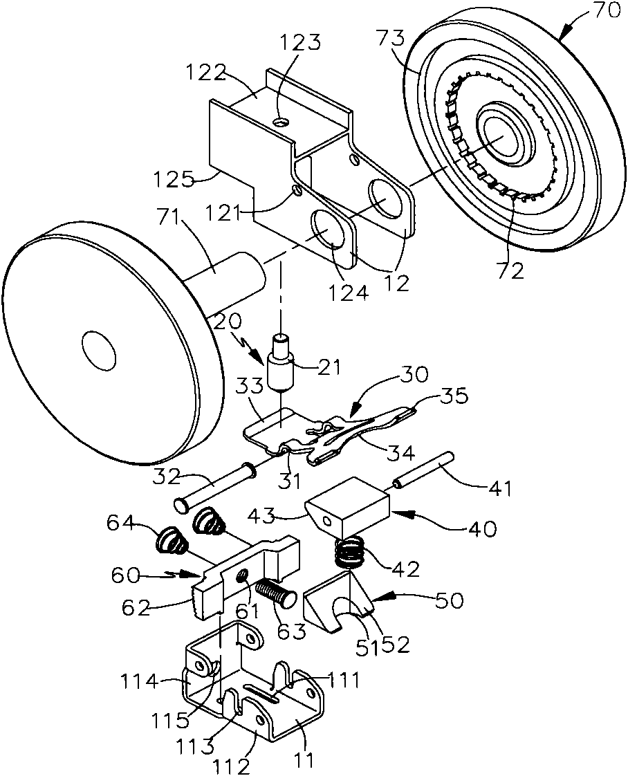
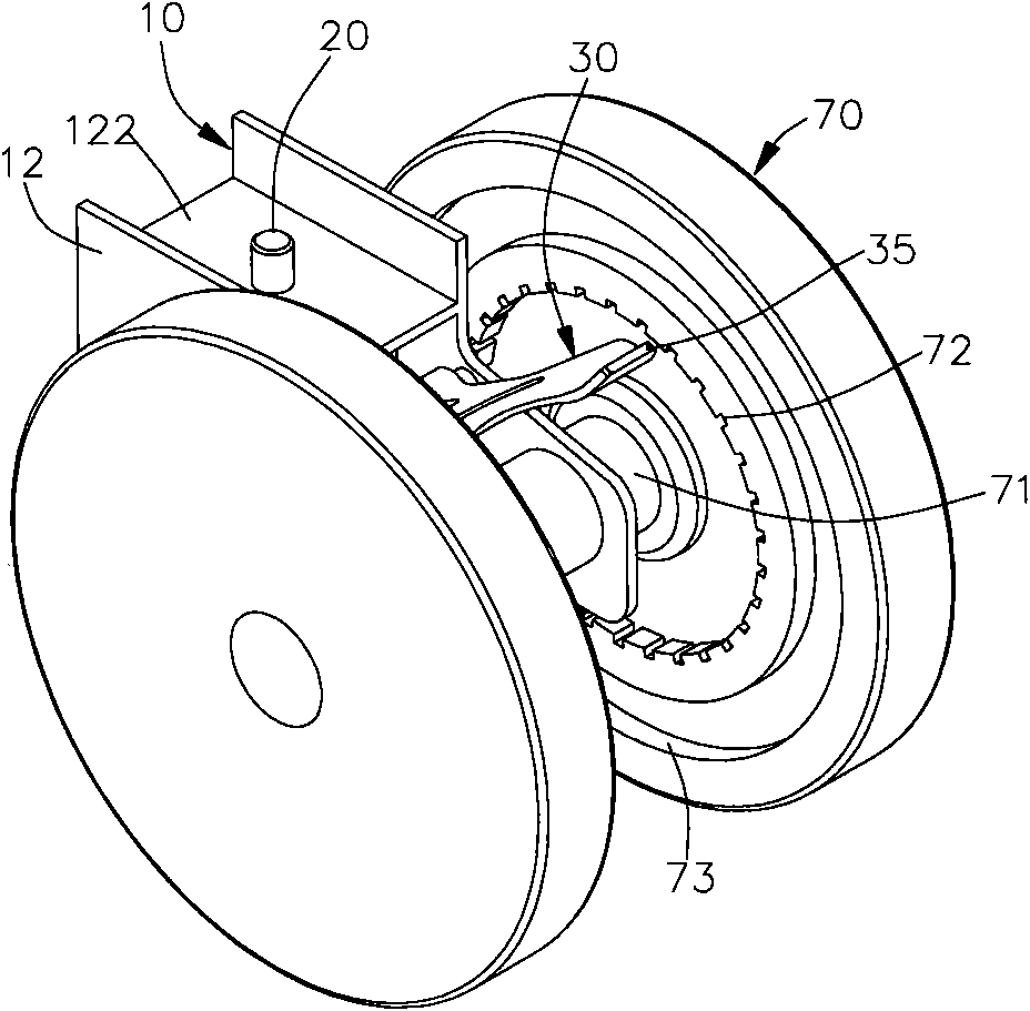
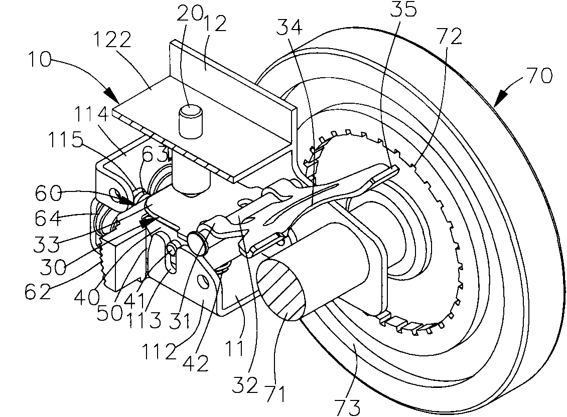
[0041] The caster with brake structure according to the present invention, the embodiment is such as Figure 1 to Figure 5 shown, including:

[0042] A frame body 10 has a bottom frame 11 and two side frames 12. The bottom frame 11 has two rails 111. The opposite sides of the bottom frame 11 have a connecting plate 112 extending vertically. Each connecting plate 112 has a vertical To the extended slit 113, the other side of the bottom frame 11 has a vertically extending baffle plate 114, the baffle plate 114 has a perforation 115, each side frame 12 is located at each connecting plate 112 of the bottom frame 11, each side frame 12 It has a pivot hole 121, a shaft hole 124 and a gap 125, and the two side frames 12 are connected by a top plate 122, the top plate 122 is located above the bottom frame 11 and has a through hole 123;

[0043] An operating piece 20 is columnar, and the middle section of the operating piece 20 has a shoulder 21, so that when one end of the operating ...


PUM


Abstract

The invention discloses a caster with a brake structure, comprising a frame body, an operation part which penetrates the frame body, a pivot piece which is rotatably pivoted on the frame body, a lifting block which is arranged on the frame body in an elastic reset lifting manner, an anti-skid block which is arranged on the frame body in an elastic reset displacement manner, and a rotating wheel which is rotatably arranged on the frame body. When the caster is positioned, the operation part is used for pushing the pivot piece to rotate, a clamping edge of the pivot piece is inserted in a positioning ditch of the rotating wheel for positioning the rotating wheel, the pivot piece simultaneously pushes the lifting block to descend, the lifting block can push and resist a sliding block to carry out horizontal displacement in the pushing and resisting means during the descending displacement, and the sliding block further pushes the anti-skid block to carry out the displacement and oppresses the oppression surface of the rotating wheel for positioning the rotating wheel, thereby simultaneously inserting the pivot piece in the positioning ditch on the inner side of the rotating wheel, using the anti-skid block to oppress the oppression surface of the rotating wheel, using the dual-positioning to achieve the effect of indeed positioning the rotating wheel, and solving the shortcoming that the positioning is not indeed caused by only using one positioning technology in the past.

Description

technical field [0001] The invention relates to a caster, in particular to a caster with a brake structure. Background technique [0002] Casters are tools installed under various equipment, cabinets, platforms, and even hospital beds. The purpose is to allow items equipped with casters to move smoothly using casters, saving the effort of handling, but when moving to a fixed point, just The casters must be positioned, so many technologies for positioning the casters have been developed on the market. Among them, the technology of using anti-sliding blocks is more common, such as the technology of Taiwan Patent Application No. 096219293 and the patent name "brake structure of casters". Use the anti-slip block to press the caster, and provide the friction force of the caster by the anti-slip block to allow the caster to be positioned. Another common technology is to use the positioning block to block the caster, such as Taiwan Patent Application No. 096218417, patent name The...

Claims


Application Information

Patent Timeline
IPC IPC(8): B60B33/00
Inventor 林青松
Owner CATIS PACIFIC MFG CORP
Why Eureka
Try Eureka