Turn-around device and turn-around method for bridge girder erection machine

The technology of a U-turn device and a bridge erecting machine, which is applied in the field of U-turn devices, can solve problems such as troublesome, time-consuming, and labor-intensive, and achieve the effects of reducing workload, improving efficiency, and saving time and labor

Inactive Publication Date: 2010-10-13
THE 1ST ENG CO LTD OF CHINA RAILWAY 25TH BUREAU GRP +1
View PDF1 Cites 13 Cited by
  • Summary
  • Abstract
  • Description
  • Claims
  • Application Information

AI Technical Summary

Problems solved by technology

In addition, in this way, the bridge erecting machine needs to be disassembled into smaller parts for transportation, and the bridge

Method used


Image

  • Turn-around device and turn-around method for bridge girder erection machine
  • Turn-around device and turn-around method for bridge girder erection machine
  • Turn-around device and turn-around method for bridge girder erection machine

Examples


Embodiment Construction

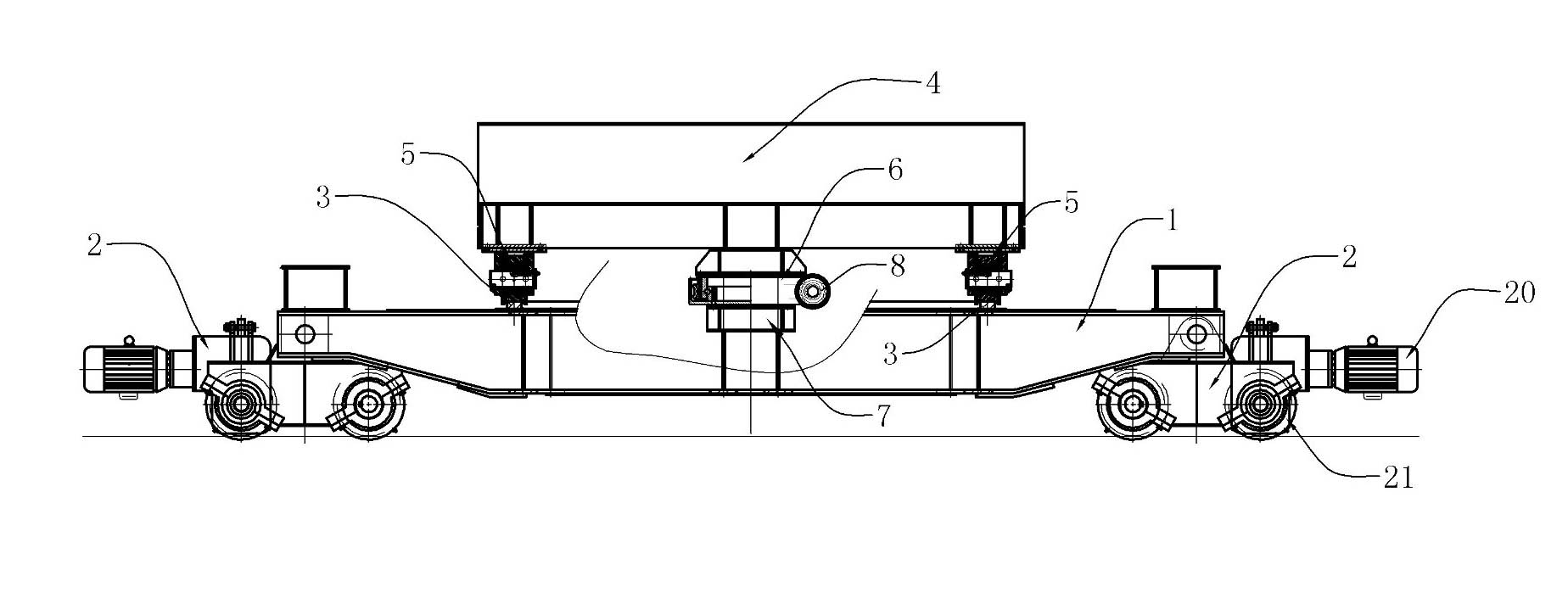
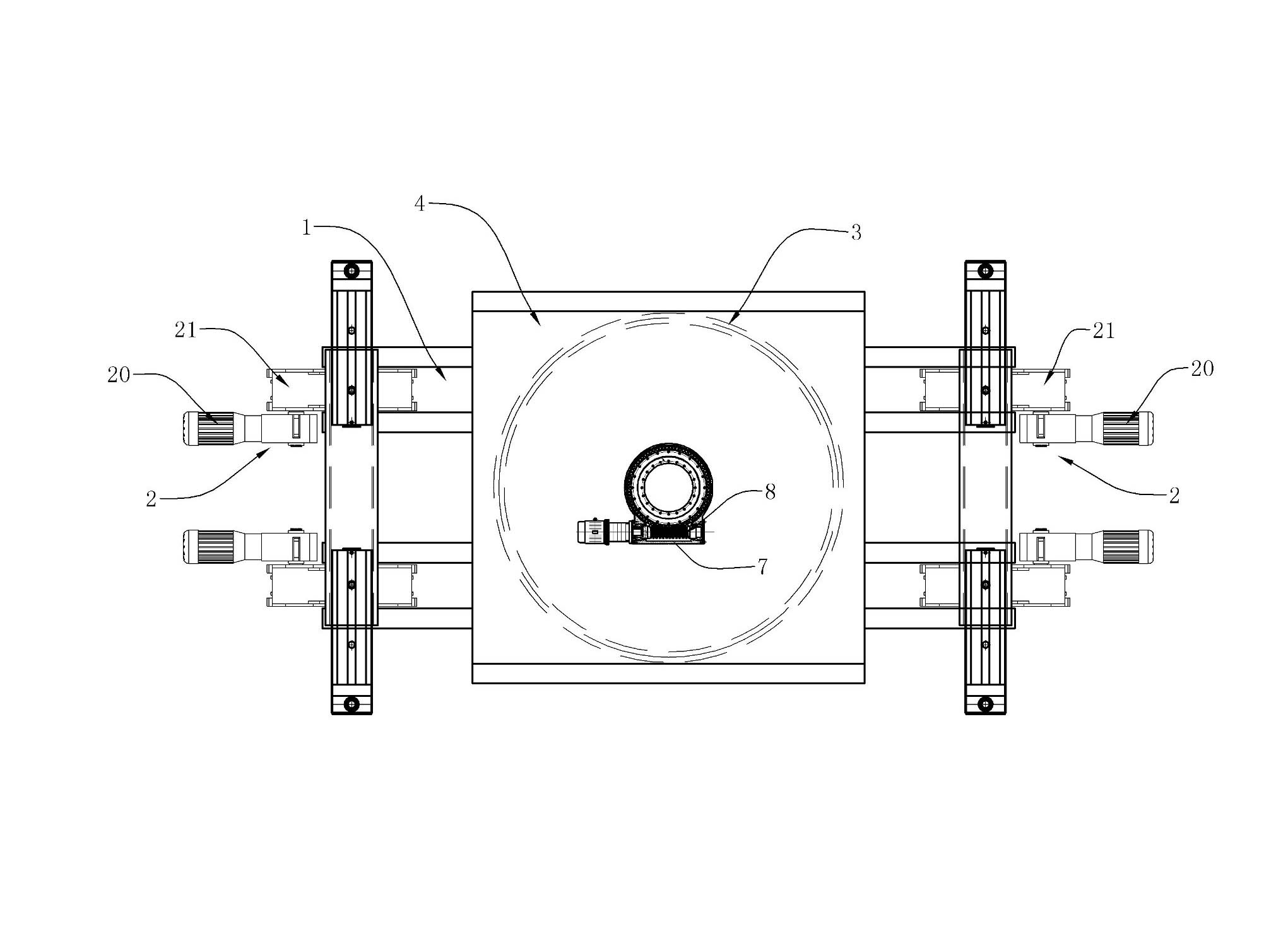
[0018] A U-turn device of a bridge erecting machine, such as figure 2 , image 3 , Figure 4 , including a vehicle frame 1 and a drive mechanism 2 for driving the vehicle frame to move along the track is installed at both ends of the vehicle frame 1. The driving mechanism can be a wheel driven by a motor 20, similar to the wheel 21 of a train, and the motor rotates to drive the wheel to rotate, thereby walking along the rail. The middle part of the frame is provided with an annular track 3, such as image 3 , the turret 4 is located above the vehicle frame 1, and can move along the circular track by placing a plurality of bearing wheels 5 in the circular track 3. The bearing wheels can be four, five, or even more, and are evenly arranged in the rotating At the bottom of the frame, a turbine 6 is also installed in the center of the bottom side of the turret 4, and the worm 8 and the turbine 6 that are installed on the vehicle frame 1 by the fixed mount 7 are engaged.

[00...


PUM


Abstract

The invention discloses a turn-around device for a bridge girder erection machine and a method for turning around a machine to be turned around by using the device. The turn-around device comprises a frame and driving mechanisms which are arranged at the two ends of the frame for driving the frame to move along a track, wherein the middle part of the frame is provided with an annular track; a rotary frame is positioned above the frame; a plurality of bearing wheels are arranged in the annular track so as to move along the annular track; the centre of the bottom side of the rotary frame is provided with a worm wheel; and a worm arranged on the frame through a fixing frame is engaged with the worm wheel. The worm is turned so as to drive the worm wheel to rotate, so the bearing wheels can move along the annular track and the rotary frame can rotate gradually. When the bridge girder erection machine is turned around, the bridge girder erection machine can be broken down into a main machine and an arm, the main machine and the arm are arranged on the rotary frame, the rotary frame is controlled to rotate the main machine and the arm for 180 degrees by driving the worm and then the main machine and the arm are reassembled so as to turn around the bridge girder erection machine. The invention has the advantages of safe operation process, simple and convenient use and high efficiency.

Description

technical field [0001] The invention relates to a bridge erecting machine used in the construction of highways and bridges, in particular to a device for turning around the bridge erecting machine; and a method for using the turning device to turn around the bridge erecting machine. Background technique [0002] The bridge erecting machine is currently the main construction machine for erecting railway T-shaped bridges. When erecting beams in the construction of new routes, or in the reconstruction of existing routes, bridge erecting machines often need to perform U-turn operations to meet the needs of on-site construction. Require. [0003] At present, the bridge erecting machine cannot realize the in-situ U-turn. During the construction, the method of finding the nearest triangular line on the existing railway route is mainly used to realize the U-turn, such as figure 1 . When making a U-turn, first disassemble the bridge erecting unit, fix it according to the requiremen...

Claims


Application Information

Patent Timeline
IPC IPC(8): E01D21/00
Inventor 张建平何功玲张建慈古辉荣姚晓虹张胜叶鹏云欧剑王李洪刘义新赖景良莫劲唐湘华
Owner THE 1ST ENG CO LTD OF CHINA RAILWAY 25TH BUREAU GRP
Why Eureka
Try Eureka