
Backlight source

A backlight and light-emitting surface technology, applied in the field of backlight, can solve problems such as poor uniformity of LED backlight, and achieve the effects of avoiding overlapping of light and dark, increasing refraction angle, and improving uniformity

Inactive Publication Date: 2010-10-13
BEIJING BOE OPTOELECTRONCIS TECH CO LTD
View PDF0 Cites 1 Cited by
  • Summary
  • Abstract
  • Description
  • Claims
  • Application Information

AI Technical Summary

Problems solved by technology

[0004] The invention provides a backlight, which is used to solve the defect of poor uniformity of the LED backlight in the prior art, and improve the uniformity of the LED backlight

Method used


Image

  • Backlight source
  • Backlight source
  • Backlight source

Examples


Embodiment Construction

[0014] The technical solutions of the embodiments of the present invention will be further described below in conjunction with the accompanying drawings and specific embodiments.

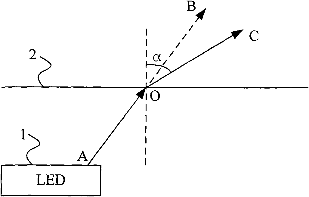
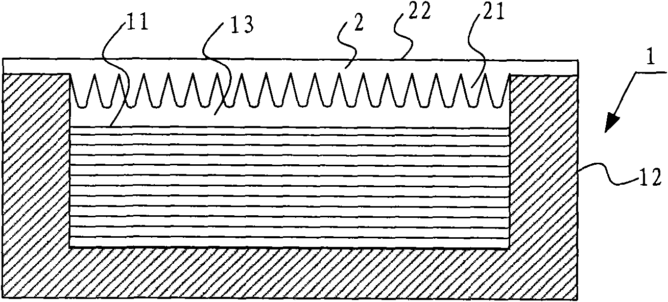
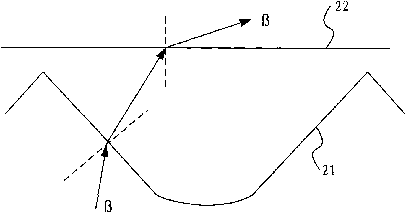
[0015] With the continuous development of LED technology, LED has gradually become the preferred light-emitting element in backlight due to its small size and high brightness. Therefore, the peripheral brightness is darker than the middle brightness, which will cause the overlapping phenomenon of light and dark among several LED illuminants, resulting in the defect of poor uniformity of LED backlight. The present invention provides a solution to the above defects The solution is that in the existing backlight using LED as the light source, in order to increase the brightness around the single LED illuminant, that is, to increase the intensity of light emitted to the periphery, a light-transmitting film is set on the light-emitting surface of each LED illuminant to play a role. It is not only transpa...


PUM


Abstract

The invention provides a backlight source comprising a light assembly formed by a plurality of LED light-emitting bodies arranged at intervals, wherein each LED light-emitting body comprises an LED light-emitting surface on which a transmitting film for improving the refracted angle of emitting light from an LED light-emitting surface is arranged in parallel. The backlight source provided by the invention improves the refracted angle of the LED emitting light through arranging the transmitting film which transmits light and makes the emitted light play diffusion action on LEDs, achieves the aim that the LED emits light uniformly, avoids the phenomenon of light and shade superposition among the LEDs, and improves the uniformity of the LED backlight source.

Description

technical field [0001] The invention relates to the technical field of liquid crystal display manufacture, in particular to a backlight source. Background technique [0002] At present, light emitting diode (Light Emitting Diode; hereinafter referred to as: LED) technology has entered a stage of rapid development, and has been involved in many different fields from ordinary daily lighting to automotive lighting. For the field of liquid crystal display, LED has gradually become the preferred light-emitting element in the field of liquid crystal display due to its small size and high brightness. size backlight market. [0003] The existing LED backlight generally includes several LEDs arranged at intervals. Due to the limitation of the coverage of the light-emitting surface of individual LEDs, that is to say, the brightness at the edge of the LEDs is weak, so there will be bright and dark alternating between several LEDs. The phenomenon of stacking causes the defect of poor ...

Claims


Application Information

Patent Timeline
Patent Type & Authority Applications(China)
IPC IPC(8): F21S8/00F21V5/00G02F1/13357F21Y101/02
Inventor 冀利林
Owner BEIJING BOE OPTOELECTRONCIS TECH CO LTD
Learn More