Snap ring-type force sensor

A force sensor and sensor technology, applied in the field of sensors, can solve problems such as single function, inability to install sensors, difficulty in ensuring test accuracy, etc., to achieve the effect of convenient installation and elimination of bending stress

Inactive Publication Date: 2010-10-13
SHANGHAI INST OF TECH
View PDF4 Cites 7 Cited by
  • Summary
  • Abstract
  • Description
  • Claims
  • Application Information

AI Technical Summary

Problems solved by technology

[0002]Existing stress testing of circular shaft members is a relatively complicated task, which must be done on the working shaft such as grinding, cleaning, attaching strain gauges and building bridges. Since it is an on-site operation, it is difficult to guarantee the test accuracy
However, due to structural reasons, the existing force sensor can only be connected to the shaft end, and cannot be connected to other parts of the shaft, and the shaft end is often unable to install the sensor.
Some attached sensors fail to solve the problem of relative displacement (slip) between the sensor and the working shaft under load and have a single function, so some composite loads cannot be tested

Method used


Image

  • Snap ring-type force sensor
  • Snap ring-type force sensor
  • Snap ring-type force sensor

Examples


Embodiment Construction

[0036] The present invention will be further described below in conjunction with the accompanying drawings and embodiments.

[0037] The sensor of the present invention is a strain gauge force sensor. The snap ring structure fixes the sensor on various working shafts. When the working shaft is deformed by the load, the sensor deforms along with it, and the strain gauge arranged on the sensor generates an output signal, which is linearly proportional to the load. Use this principle to measure the load.

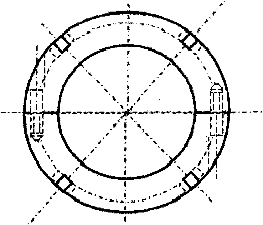
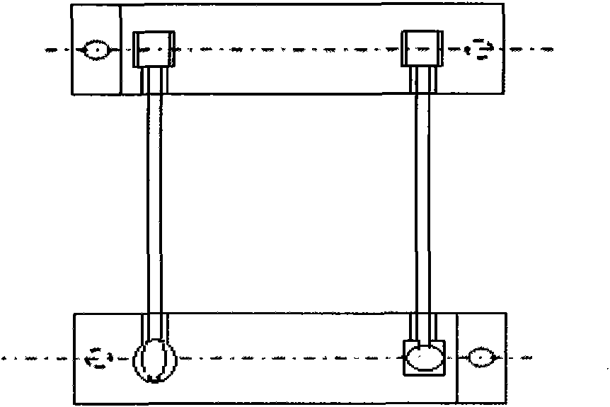
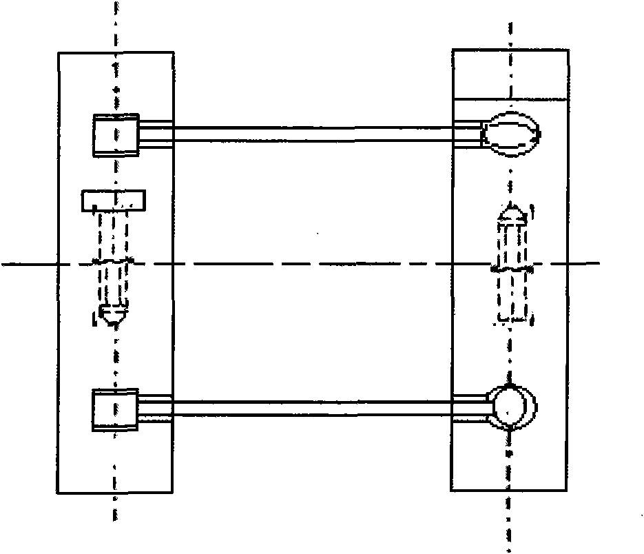
[0038] Such as Figure 1 to Figure 3 As shown, the snap ring force sensor includes a semicircular ring, a sensor elastic body, and a strain gauge. The two semicircular rings are connected by bolts to form a snap ring. The two snap rings are connected by the sensor elastic body, and the sensor elastic body is pasted There are resistance strain gauges.

[0039] When measuring tension and pressure, one end of the elastic body is T-shaped ( Figure 12 , 13), it is longitudinal...


PUM

PropertyMeasurementUnit
diameteraaaaaaaaaa
diameteraaaaaaaaaa

Abstract

The invention relates to a snap ring-type force sensor. When pulling force or pressure force is detected, a T-shaped head of one end of an elastic body is connected with a T-shaped groove of a half ring in longitudinally-matched manner, and the other longitudinal elliptic end of the elastic body is connected with a round groove of the other half ring in a matched manner; and four resistance foil gauges are stuck on four sides of the elastic body of the sensor respectively, wherein four sides are parallel with an axes, two resistance foil gauges are stuck longitudinally while another two resistance foil gauges are stuck horizontally, directions of corresponding faces are the same and are on the same transversal surface, and the longitudinal position is h2+H2+(3-4)mm away from the top end of a rectangular head. When torque force is detected, one end of the elastic body is T-shaped and the other end of the elastic body is latitudinal elliptic; and two resistance foil gauges are stuck on two corresponding sides of the elastic body of the sensor respectively, wherein the two corresponding sides are at the depth of section, directions of the corresponding sides are the same and are on the same transversal surface, and the longitudinal position is h2+H2+(3-4)mm away from the top end of a rectangular head. The sensor can well transmit bending force generated by pulling force, pressing and torque, and is not affected by other deformation. Various functions of the sensor can be realized by using different elastic body combination.

Description

technical field [0001] The invention relates to a sensor, in particular to a strain type force sensor. Background technique [0002] Existing stress testing of circular shaft members is a relatively complicated task. Works such as grinding, cleaning, attaching strain gauges, and bridge assembly must be performed on the working shaft. Since it is an on-site operation, it is difficult to guarantee the test accuracy. However, due to structural reasons, the existing force sensor can only be connected to the shaft end, and cannot be connected to other parts of the shaft, and the shaft end is often unable to install a sensor. Some attached sensors fail to solve the problem of relative displacement (sliding) between the sensor and the working shaft under load and have a single function, so some compound loads cannot be tested. . It is also affected by other deformations under load. Contents of the invention [0003] The present invention is to provide a clasp-type force sensor...

Claims


Application Information

Patent Timeline
Patent Type & Authority Applications(China)
IPC IPC(8): G01L1/22
Inventor 夏荫培石钢杨斐瞿薇
Owner SHANGHAI INST OF TECH
Why Eureka
Try Eureka