Large air-cooled turbo-generator with circumferential mixed ventilation cooling structure

A turbo-generator, ventilation and cooling technology, which is applied in cooling/ventilation devices, electrical components, electromechanical devices, etc., can solve the problem that the single-unit capacity of the turbo-generator cooling technology cannot be taken into account at the same time, so as to improve the cooling effect and reduce the power. , the effect of large heat dissipation coefficient

Active Publication Date: 2011-12-07
HARBIN UNIV OF SCI & TECH
View PDF0 Cites 2 Cited by
  • Summary
  • Abstract
  • Description
  • Claims
  • Application Information

AI Technical Summary

Problems solved by technology

[0003] The purpose of the present invention is to solve the problem that the cooling technology of the existing turbo-generator and the technology of increasing the capacity of the single unit cannot be taken into account at the same time, and to provide a large-scale air-cooled turbo-generator with a circumferential mixed ventilation cooling structure

Method used


Image

  • Large air-cooled turbo-generator with circumferential mixed ventilation cooling structure
  • Large air-cooled turbo-generator with circumferential mixed ventilation cooling structure
  • Large air-cooled turbo-generator with circumferential mixed ventilation cooling structure

Examples


specific Embodiment approach 1

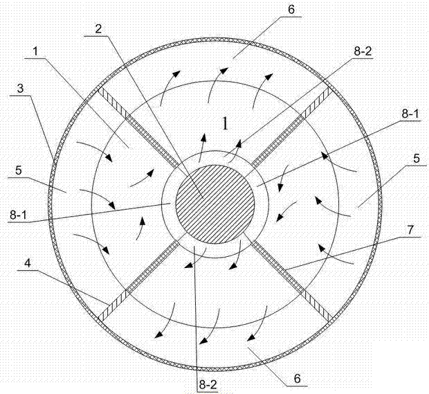
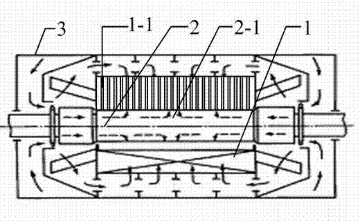
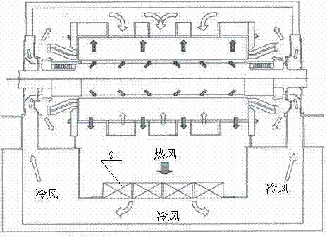
[0011] Specific implementation mode one: the following combination figure 1 , figure 2 and image 3 Describe this embodiment, this embodiment includes a stator 1, a rotor 2 and a casing 3, an air gap is formed between the outer surface of the rotor 2 and the inner surface of the stator 1, and the stator 1 is housed inside the casing 3, It also includes four axial rubber partitions 4 and a cooler 9, the four axial rubber partitions 4 are evenly arranged between the inner circular surface of the casing 3 and the outer circular surface of the stator 1 along the circumferential direction, forming Two opposite cold wind areas 5 and two opposite hot air areas 6 , the two opposite hot air areas 6 communicate with the inlet of the cooler 9 .

[0012] In this embodiment, a special oil-resistant and electric-resistant synthetic rubber strip partition is used between the inner circular surface of the casing 3 and the outer circular surface of the stator 1 to divide it into four parts ...

specific Embodiment approach 2

[0013] Specific implementation mode two: the following combination figure 1 and figure 2 Describe this embodiment, the difference between this embodiment and Embodiment 1 is that it also includes four air gap baffles, and the air gap segment corresponding to the stator arc segment corresponding to the cold wind area 5 is the air gap arc segment 8 in the cold wind area -1, there are two air gap arc sections 8-1 in the cold wind zone, and an air gap baffle plate is respectively arranged on the two end faces of the air gap arc section 8-1 in the cold wind zone. Other components and connections are the same as those in Embodiment 1.

[0014] The setting of the air gap baffle can prevent the air volume at the entrance of the air gap from affecting the cold wind area, and even cause the effect of air recharge. The mixing of the air volume at the outlet of the cold air area can reduce the temperature of the air entering the hot air area.

[0015] working principle:

[0016] The ...

specific Embodiment approach 3

[0017] Specific implementation mode three: the following combination figure 1 Describe this embodiment, the difference between this embodiment and Embodiment 1 or 2 is that it also includes four ventilation channel steels 7, the four ventilation channel steels 7 are evenly arranged along the circumferential direction of the stator 1, and the four ventilation channel steels The channel steel 7 divides the stator 1 into four regions, and the arc segments of the outer wall of the stator 1 corresponding to the four regions correspond to the arc segments where the cold wind zone 5 and the hot wind zone 6 are respectively located. Other compositions and connections are the same as those in the first or second embodiment.

[0018] In this embodiment, four ventilation channel steels 7 are used in the area of ​​the stator 1 to divide the stator 1 into the same four areas on the circumference, and the stator 1 is formed into a petal layout. This petal-type layout structure separates th...


PUM


Abstract

The invention relates to a large air-cooled turbo-generator with a circumferential mixed ventilation cooling structure, which belongs to the technical field of motors. The large air-cooled turbo-generator can solve the problem that the existing cooling technology of the turbo-generator and the improvement technology of the single unit capacity can not be simultaneously integrated. The large air-cooled turbo-generator comprises a stator, a rotor and a housing, wherein an air gap is arranged between the surface of an outer circle of the rotor and the surface of an inner circle of the stator, the stator is covered in the housing, the large air-cooled turbo-generator further comprises four axial rubber separators and a cooler, the four axial rubber separators are uniformly arranged between the surface of the inner circle of the housing and the surface of the outer circle of the stator along the circumferential direction, two opposite cold air areas and two opposite hot air areas are formed, and the two opposite hot air areas are communicated with an inlet of the cooler. The large air-cooled turbo-generator with the circumferential mixed ventilation cooling structure is used for cooling the large air-cooled turbo-generator.

Description

technical field [0001] The invention relates to a large-scale air-cooled turbogenerator with a circumferential mixed ventilation cooling structure, which belongs to the technical field of motors. Background technique [0002] In order to keep the temperature of the components in the turbogenerator within the allowable limits of insulating materials and metal materials, the loss of the components must be transferred to the surrounding cooling medium in the form of heat during the operation of the turbogenerator to effectively Implement the cooling of various components in the turbo-generator. The improvement of the unit capacity of the turbogenerator is mainly achieved by increasing the electromagnetic parameters in the design due to the limitation of the stator transportation size, the rotor forging and the rotor deflection. And because the magnetic-permeable material still has the problem of saturation, the improvement of the unit capacity of the turbo-generator is mainly...

Claims


Application Information

Patent Timeline
Patent Type & Authority Patents(China)
IPC IPC(8): H02K9/02H02K9/06
Inventor 李伟力管春伟
Owner HARBIN UNIV OF SCI & TECH
Why Eureka
Try Eureka