
Compact injector device with two armatures

A technology of injection device and armature, which is applied in the directions of fuel injection device, charging system, condensed fuel collection/return, etc., can solve the problems of large structure space and complex structure, and achieve the effect of simple cost, compact structure and reduced number of parts

Inactive Publication Date: 2012-06-20
ROBERT BOSCH GMBH
View PDF1 Cites 0 Cited by
  • Summary
  • Abstract
  • Description
  • Claims
  • Application Information

AI Technical Summary

Problems solved by technology

However, the structure is relatively complex and the device occupies a large construction space

Method used


Image

  • Compact injector device with two armatures
  • Compact injector device with two armatures
  • Compact injector device with two armatures

Examples


Embodiment Construction

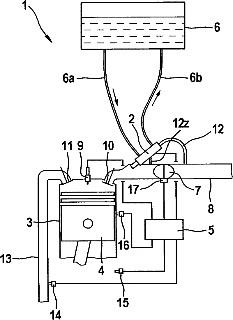
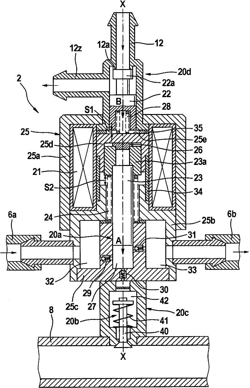
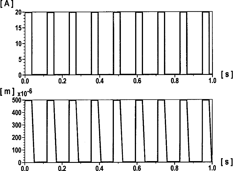
[0021] The following reference Figure 1 to 4 A small engine 1 having the injection device according to the first embodiment of the present invention will be described in detail.

[0022] figure 1 The structure of a small engine 1 configured as a single-cylinder engine is schematically shown. The small engine 1 includes a cylinder 3, a piston 4 capable of reciprocating inside it, a control unit 5 and an oil tank 6. The fuel tank 6 is connected to the injection assembly 2 through a fuel input line 6a. A fuel return line 6b returns to the fuel tank 6 from the injection assembly 2. As by figure 1 In a schematic representation, the fuel tank 6 is arranged above the injection assembly 2. As a result, fuel flows to the injection assembly 2 through the fuel supply line 6a based on gravity. The injection assembly 2 is represented very generally and includes a fuel pump, an injector with a combined pressure regulator and an air regulator, so that the injection assembly 2 is very compa...


PUM


Abstract

The invention relates to an injector device, comprising a fuel pump (20a), a pressure regulator (20b), an injector (20c) and a pneumatic actuator (20d), characterised in that the fuel pump (20a), the injector (20c) and the pneumatic actuator (20d) are integral components of an injection module (2), the pressure regulator (20b) is integral component of the injector (20c) and the injection device has just one further actuator which operates both the fuel pump (20a) and the pneumatic actuator (20d), wherein said actuator has a coil (21), a first armature (22) and a second armature (23a).

Description

Technical field [0001] The invention relates to an injection device having a fuel pump, a pressure regulator, an injector and an air regulator in a compact structure. Background technique [0002] Various configurations of spray devices are known from the prior art. Especially for reasons of cost and structure, a small internal combustion engine with only one or two cylinders and a small working volume requires a unique technical solution. The application fields of such small internal combustion engines are, for example, two-wheeled vehicles, three-wheeled vehicles or lawn mowers. The known injection device usually includes a fuel pump with a pressure regulator in the fuel tank, wherein the fuel pump delivers fuel with a certain pressure to a pipeline, such as a "rail". There is an ejector at the end of the pipeline, which is controlled by a control device. The fuel is injected into the intake pipe or directly into the combustion chamber. However, this type of injection devic...

Claims


Application Information

Patent Timeline
Patent Type & Authority Patents(China)
IPC IPC(8): F02M57/02F02M37/02F02M37/00
CPCY02T10/126F02M37/0052F02M37/0029F02M33/08F02M57/027
Inventor C・拜尔U・西贝尔
Owner ROBERT BOSCH GMBH
Learn More