
Detection system based on microfluidic technology

A microfluidic technology and detection system technology, which is applied in the direction of laboratory containers, instruments, laboratory utensils, etc., can solve problems such as complex operation, and achieve the effects of convenient conduction area, simple operation, and simple structure

Active Publication Date: 2019-09-13
佛山市麦控智能科技有限公司
View PDF11 Cites 1 Cited by
  • Summary
  • Abstract
  • Description
  • Claims
  • Application Information

AI Technical Summary

Problems solved by technology

For now, the structure and operation of the existing liquid path sampling system are complicated

Method used


Image

  • Detection system based on microfluidic technology
  • Detection system based on microfluidic technology
  • Detection system based on microfluidic technology

Examples


Embodiment 1

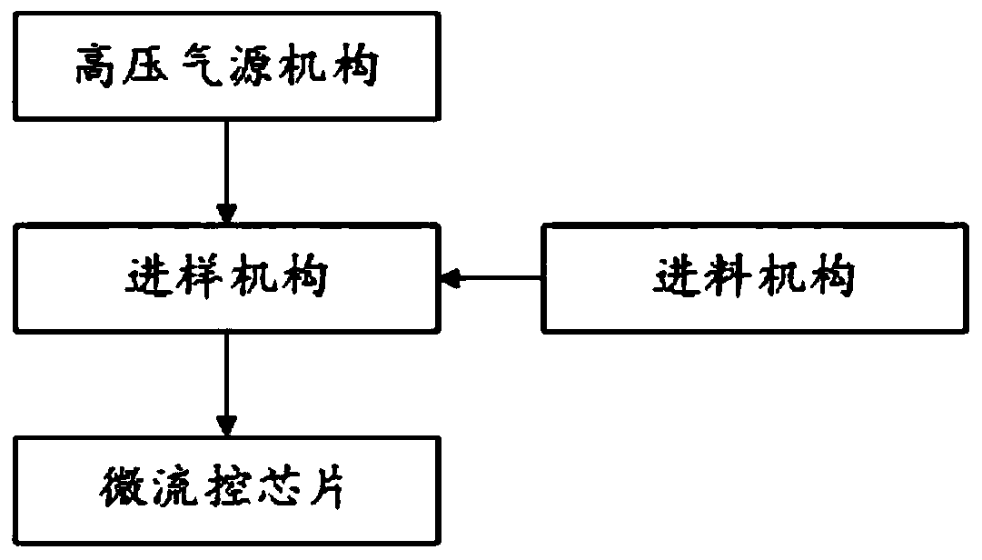
[0029] combine figure 1 As shown, this embodiment provides a detection system based on microfluidic technology, which includes a high-pressure gas source mechanism, a sample feeding mechanism 200, a feeding mechanism 1100 and a microfluidic chip, and the feeding mechanism 1100 is used to add samples In the sampling mechanism 200, the high-pressure gas source mechanism is used to provide a high-pressure gas source to the sampling mechanism 200 to press the sample in the sampling mechanism 200 into the microfluidic chip, and the microfluidic chip is used to analyze and process the sample.

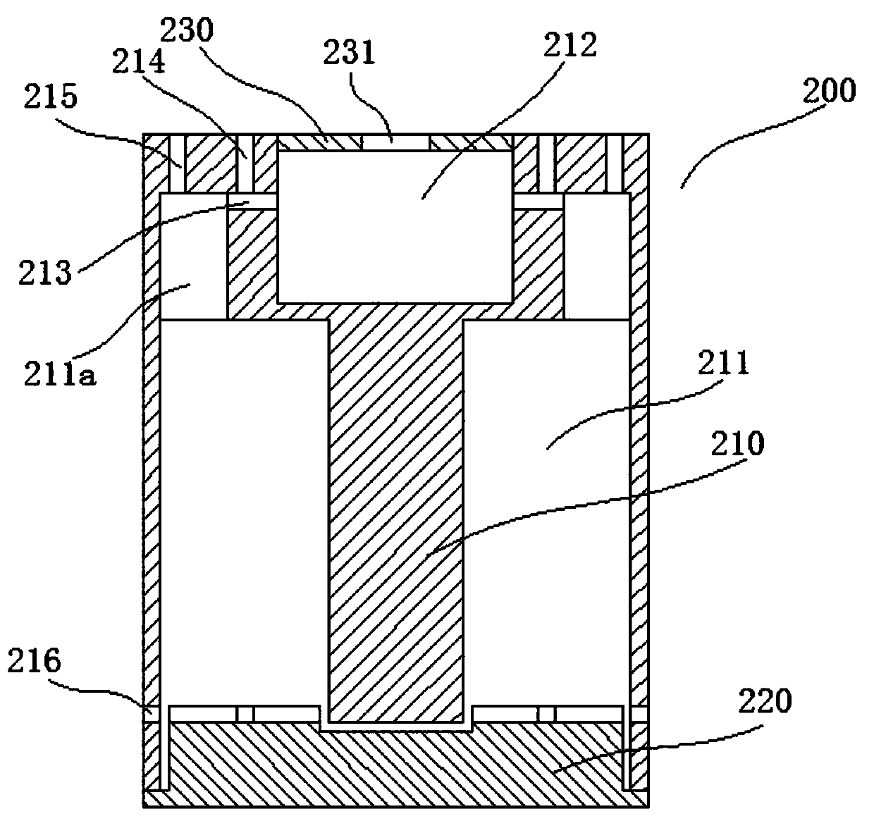
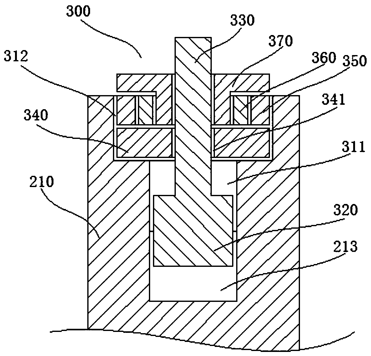
[0030] Such as figure 2 As shown, the sampling mechanism 200 includes a cylindrical sampling mechanism main body 210, and a plurality of independent sample cavities 211 are arranged in the sampling mechanism main body 210; the sample cavities 211 extend axially inward from the lower end surface of the sampling mechanism main body 210 The lower end of the main body 210 of the sampling mechan...


PUM


Abstract

The invention relates to the field of microfluidic technology, particularly to a detection system based on microfluidic technology. The detection system comprises a high-pressure gas source mechanism,a sample introduction mechanism, a feeding mechanism and a microfluidic chip, wherein the feeding mechanism is used for adding a sample into the sample introduction mechanism; the high-pressure gas source mechanism is used for supplying a high-pressure gas source to the sample introduction mechanism to press the sample in the sample introduction mechanism into the microfluidic chip; and the microfluidic chip is used for analyzing the sample. The detection system of the invention is simple in structure and easy to operate.

Description

technical field [0001] The invention relates to the field of microfluidic technology, in particular to a detection system based on microfluidic technology. Background technique [0002] Microfluidics (Microfluidics) refers to the science and technology involved in the use of micropipes (tens to hundreds of microns in size) to process or manipulate tiny fluids (nanoliters to attic liters in volume). , fluid physics, microelectronics, new materials, emerging interdisciplinary disciplines of biology and biomedical engineering. Because of the characteristics of miniaturization and integration, microfluidic devices are usually called microfluidic chips, also known as lab on a chip (Lab on a Chip) and micro-Total Analytical System (micro-Total Analytical System). The early concept of microfluidics can be traced back to the gas chromatograph produced on silicon wafers by photolithography in the 1870s, and then developed into microfluidic capillary electrophoresis and microreactors...

Claims


Application Information

Patent Timeline
Patent Type & Authority Applications(China)
IPC IPC(8): B01L3/00G01N35/10
CPCB01L3/5027G01N35/10G01N2035/1034
Inventor 章伟
Owner 佛山市麦控智能科技有限公司
Learn More