Eureka AIR delivers breakthrough ideas for toughest innovation challenges, trusted by R&D personnel around the world.

Compressor

A technology for compressors and compressor impellers, which is applied in the field of compressors and can solve problems such as delayed surge

Inactive Publication Date: 2010-10-20
CUMMINS TURBO TECH
View PDF6 Cites 2 Cited by
  • Summary
  • Abstract
  • Description
  • Claims
  • Application Information

AI Technical Summary

Problems solved by technology

In these cases, the MWE slots allow the flow to be reversed (which is common in some compressors) and recirculated into the suction, thus delaying surge

Method used


Image

  • Compressor
  • Compressor
  • Compressor

Examples


Embodiment Construction

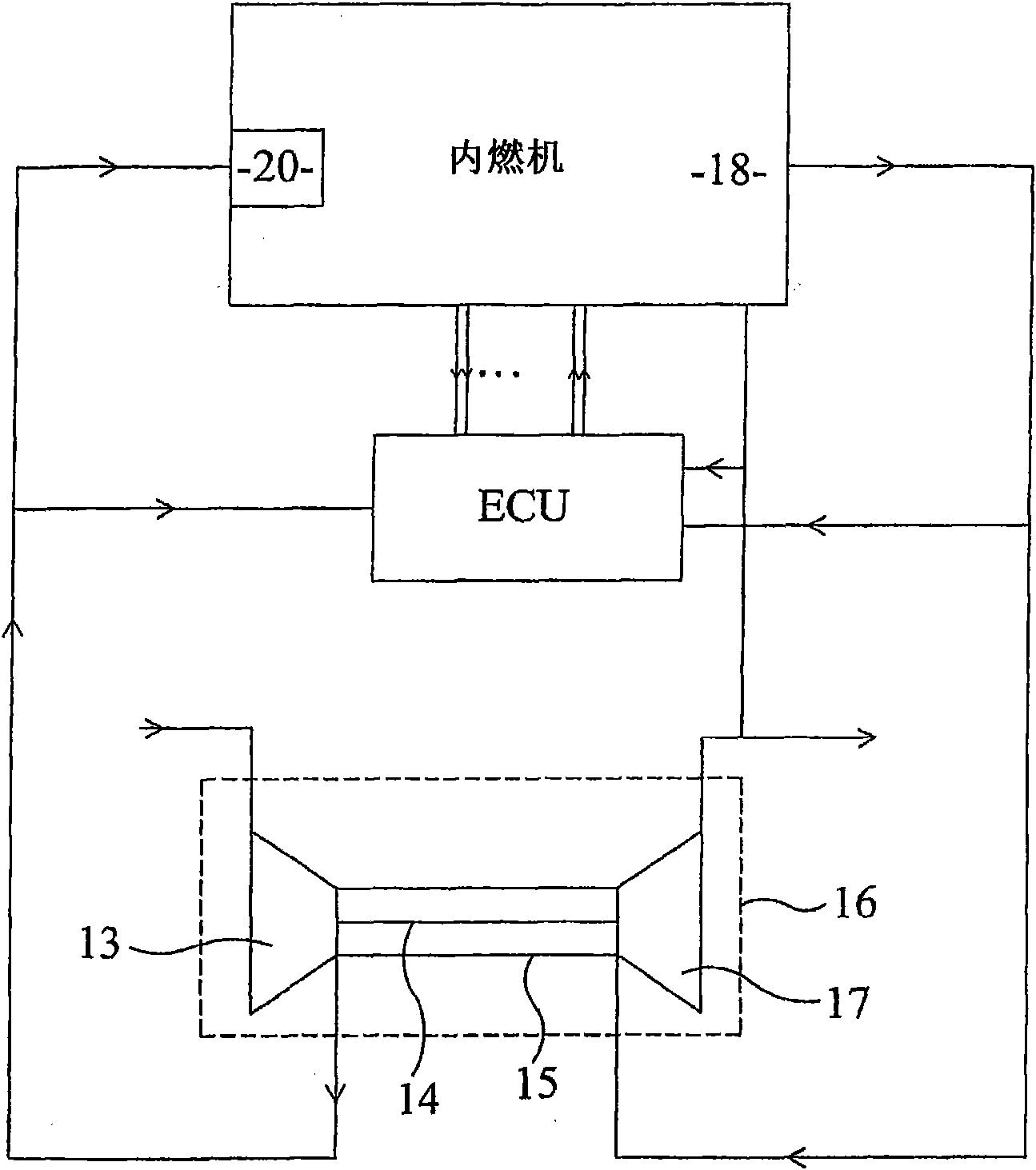
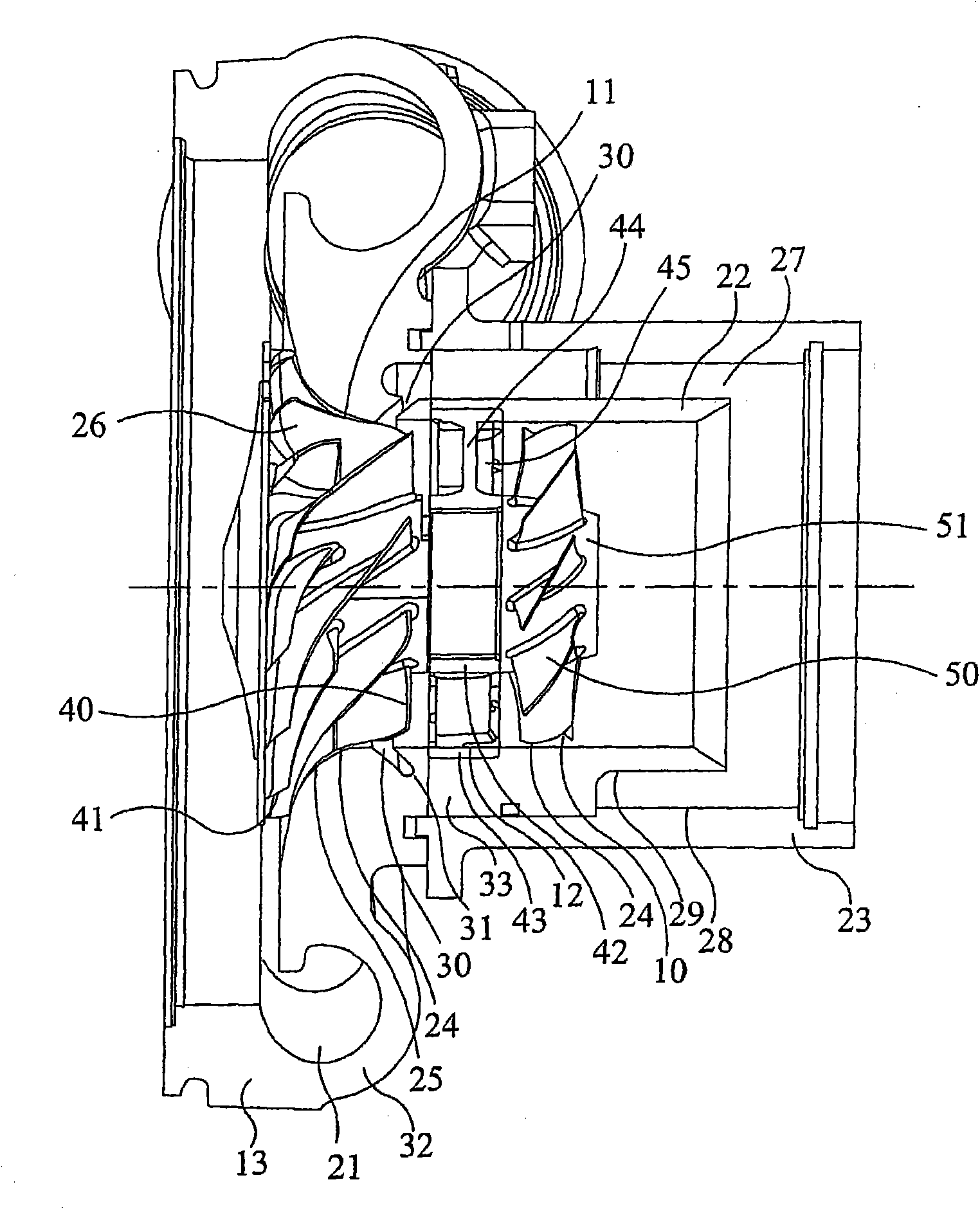
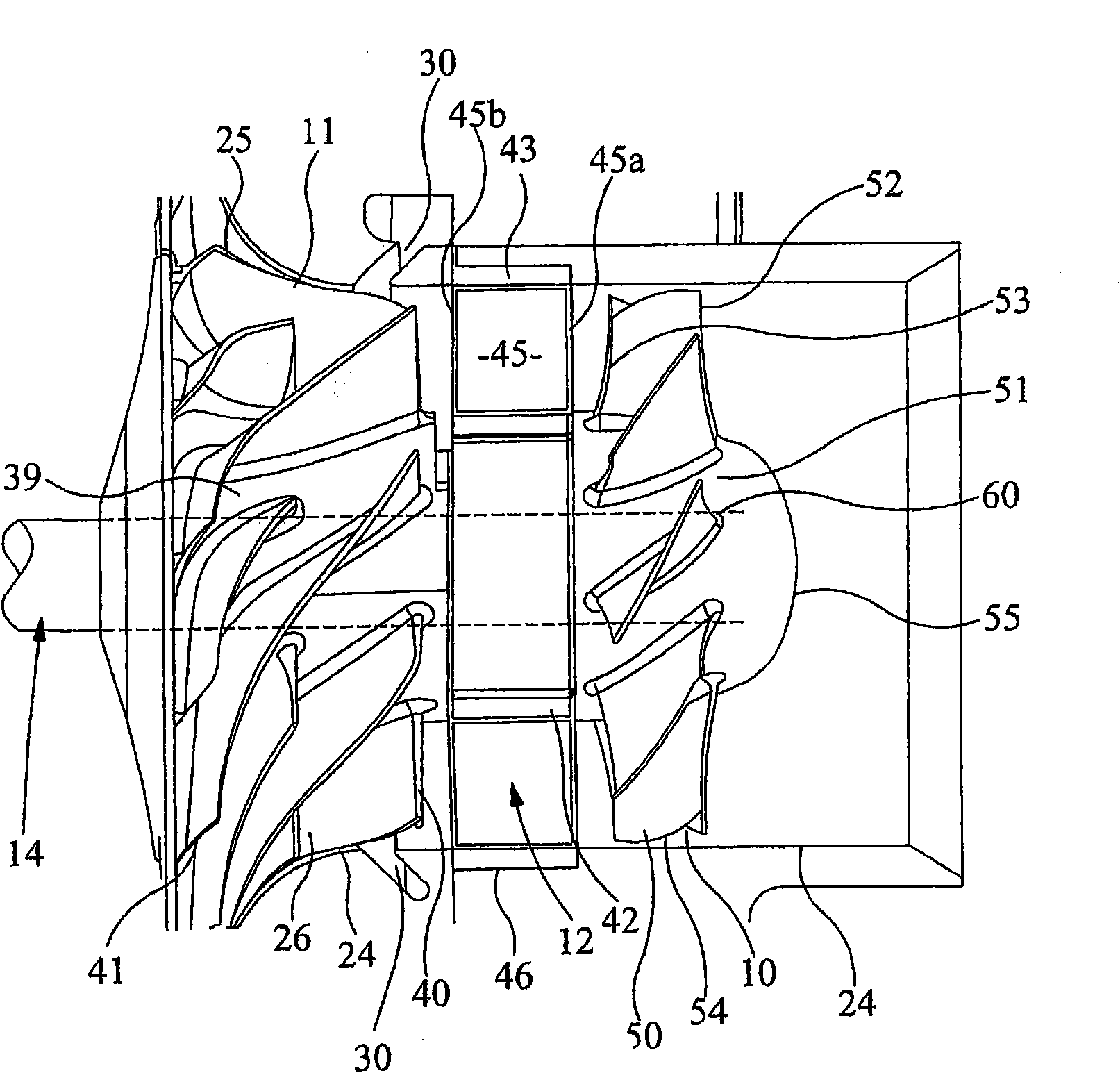
[0073] figure 1 Shows the compressor of the invention, belonging to the field of turbochargers fitted to internal combustion engines. figure 2 and image 3 A detailed enlarged exemplary embodiment showing compressor details. The compressor shown is a two-stage compressor for high compression ratios and includes an axial compressor wheel 10 upstream of a radial (centrifugal) compressor wheel 11 and passing through an intermediate axial The stator 12 is spaced apart from the radial compressor wheel 11 . The impellers 10, 11 are mounted on a common rotating shaft 14 (only image 3 shown), the common axis of rotation 14 revolves around figure 2 The compressor axis indicated by the dotted line rotates.

[0074] The compressor casing 13 is connected to a bearing housing 15 of the turbocharger 16 and the shaft 14 is designed to support an exhaust turbine 17 which is arranged on the other side of the bearing housing 15 . In operation, exhaust gas from the internal combustion e...


PUM


Abstract

A compressor typically for use in a turbocharger comprises a downstream radial compressor impeller wheel (11), an upstream axial compressor impeller wheel (10) and an intermediate stator (12). The compressor housing (13) has an inlet (19) with inner and outer walls (22, 23) that define between them an MWE gas flow passage (27). An upstream opening defined by the flow passage (27) provides communication between said passage and the intake (19) and at least one first slot (30) downstream of the upstream opening provides communication between the passage (27) and the inner surface (24) of the inner wall (22). The stator (12) comprises a plurality of fixed vanes (45) and is disposed in the inner wall (22) of the inlet between the radial and axial impeller wheels (10, 11). The position of the slot (30) can be at one of several positions along the gas flow passage (27). In other embodiments there are second and third slots (70, 71) and the flow passage (27) is divided into two parts (27a, 27b). All the arrangements are designed to improve the compressor map with.

Description

technical field [0001] The invention relates to a compressor, in particular to a multi-stage compressor suitable for a turbocharger. Background technique [0002] The compressor includes an impeller carrying a plurality of blades (or vanes) mounted on a shaft for rotation within the compressor housing. Rotation of the impeller causes gas (eg, air) to be drawn into the impeller and delivered to an outlet chamber or channel. In the case of radial or centrifugal compressors, the outlet passage is in the form of a wrap defined by the compressor casing surrounding the impeller, while in the case of axial compressors the gas is discharged axially. [0003] A turbocharger is a well-known device that supplies air to an intake port of an internal combustion engine at a pressure higher than atmospheric pressure (supercharging), and is widely used in automobiles and the like. The compressors of the turbochargers are driven by an exhaust turbine mounted on a common shaft. Exhaust gas...

Claims


Application Information

Patent Timeline
Patent Type & Authority Applications(China)
IPC IPC(8): F04D27/02F02C6/12
CPCY10S415/914F04D29/685F05B2220/40F04D29/4206F04D27/02F04D29/681F04D19/00F04D27/0215F04D29/4213F04D17/025F04D27/0207
Inventor 巴赫拉姆·尼克波尔
Owner CUMMINS TURBO TECH
Why Eureka
Eureka Blog
Learn More