
Compressor blade with dovetail slotted to reduce stress on the airfoil leading edge

a technology of compressor blades and leading edges, applied in the field of compressor blades, can solve the problems of reducing affecting the service life of compressor blades, so as to reduce the centrifugal and vibratory load

Inactive Publication Date: 2005-06-07
GENERAL ELECTRIC CO
View PDF31 Cites 25 Cited by
  • Summary
  • Abstract
  • Description
  • Claims
  • Application Information

AI Technical Summary

Benefits of technology

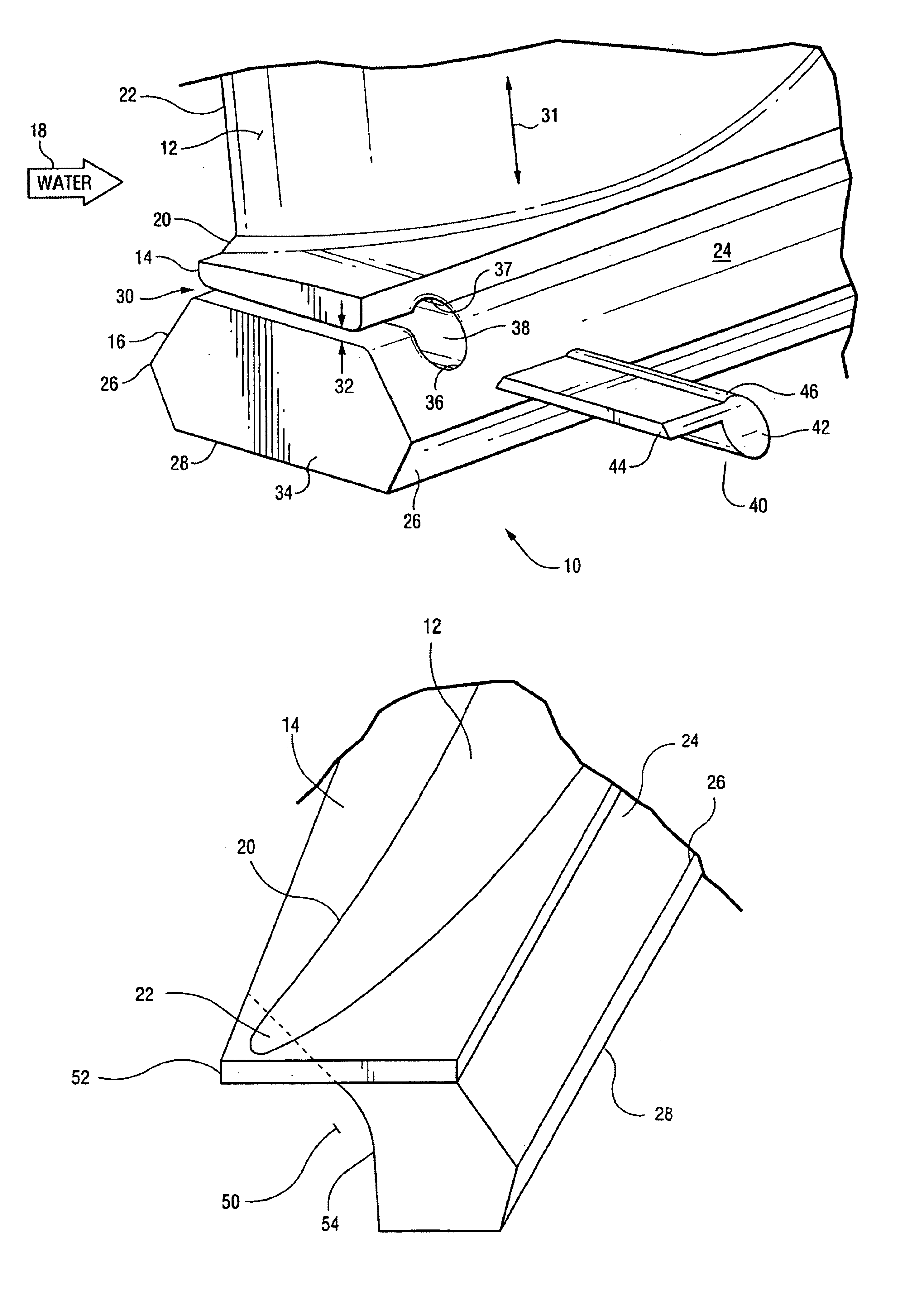
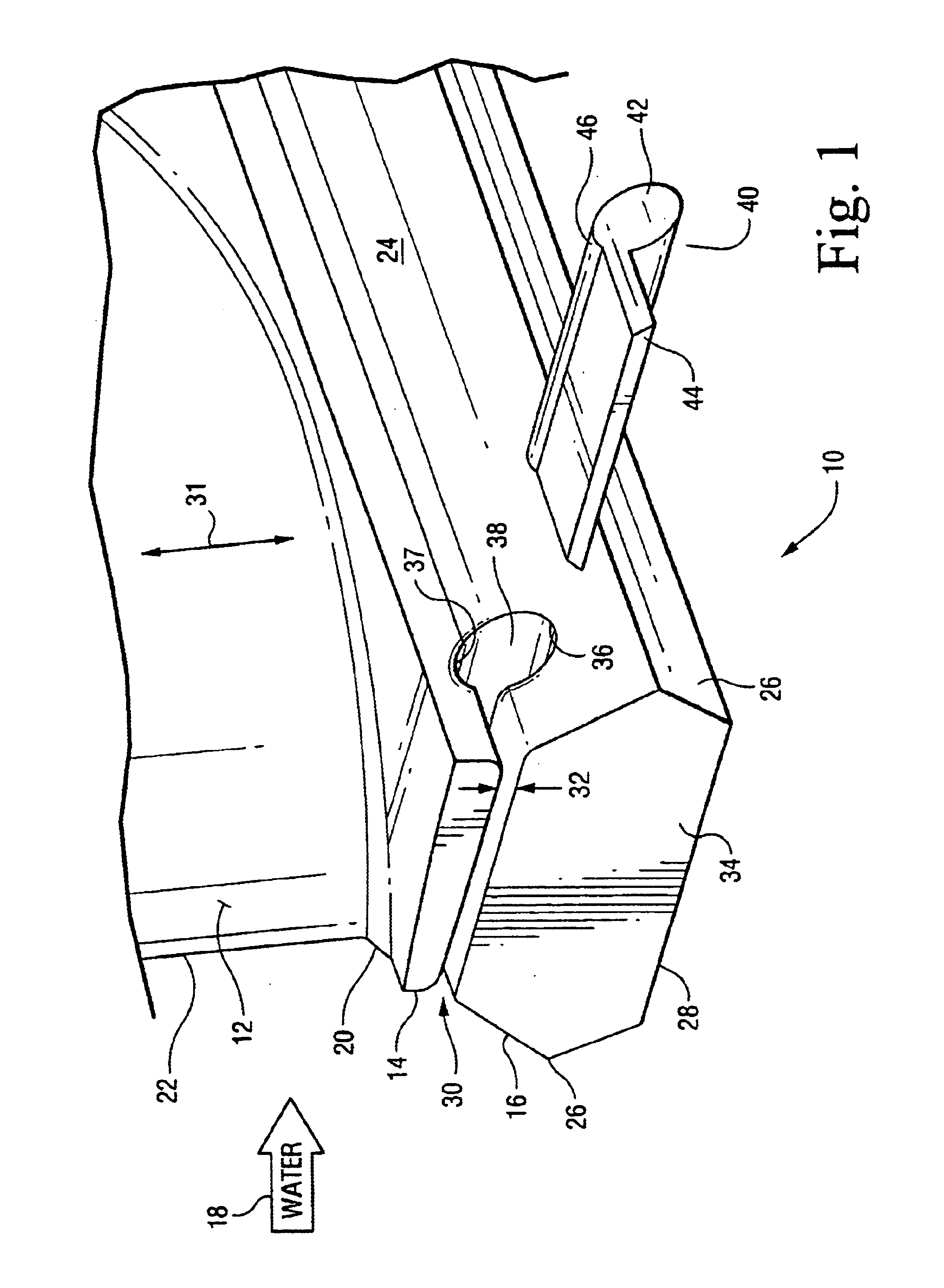
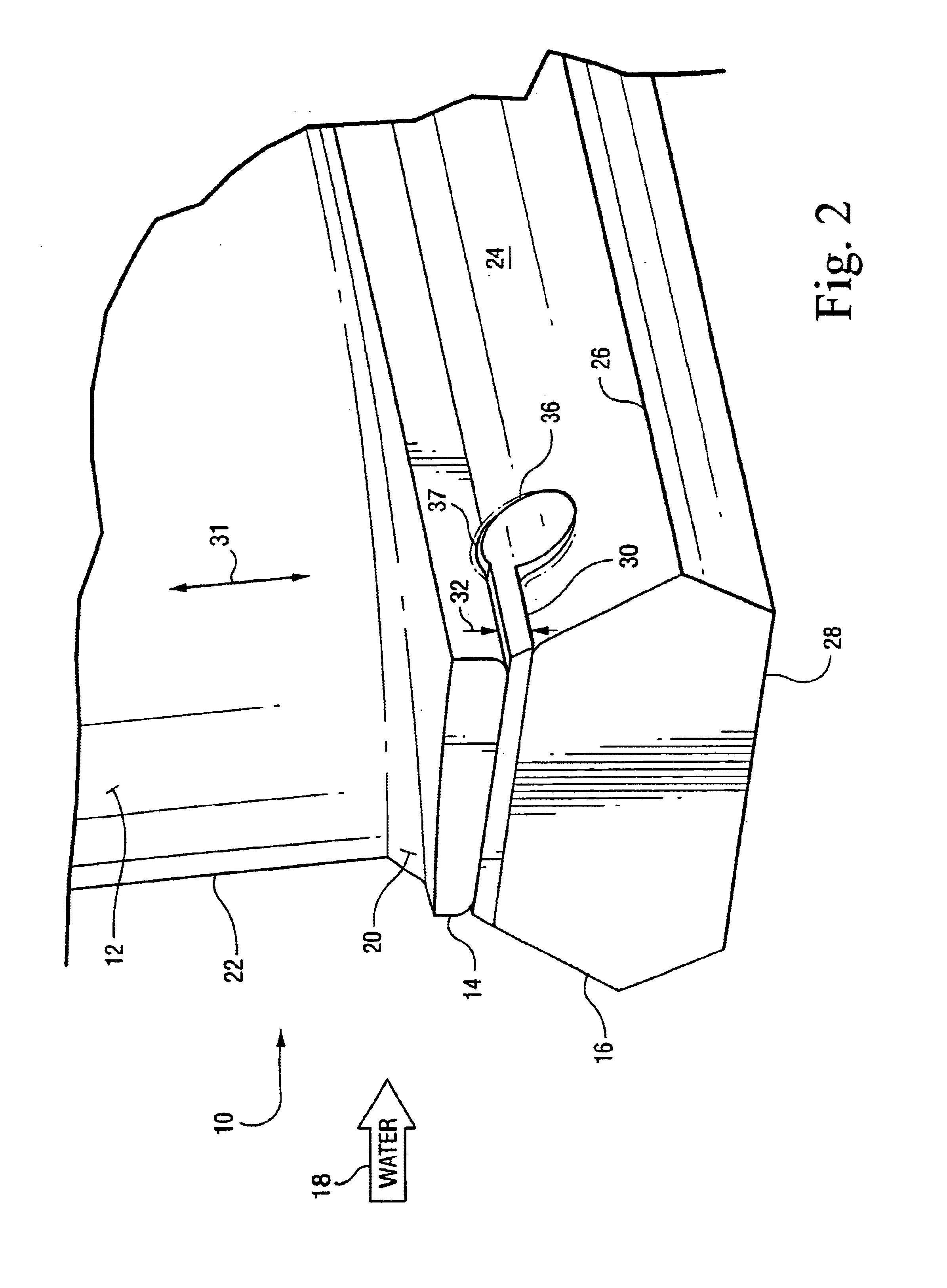
[0008]In a second embodiment, the invention is a method for unloading centrifugal stresses from a leading edge of an airfoil of a compressor blade having a platform and a dovetail, the method comprising: generating a slot in the dovetail below a front portion of the platform, wherein the slot underlies the leading edge of the airfoil; forming a cylindrical aperture at an end of the slot, wherein said cylindrical aperture is generally parallel to the platform and extends through the dovetail, and by generating the slot with the cylindrical, reducing centrifugal and vibratory load on at least the root of the leading. The blade may be a first stage compressor blade.

Problems solved by technology

However, the impact of the water on the first stage blades tends to erode the leading edge of those blades especially at their roots, which is where the blade airfoil attaches to the blade platform.
The blade is under tremendous stress due to centrifugal forces and vibration due to the airflow and the compressor machine.
These stresses tear at the pit and crevices and lead to a high cycle fatigue (HCF) crack in the blade.
Once a crack develops, the high steady state stresses due to the centrifugal forces that act on a blade and the normal vibratory stresses on the blade can cause the crack to propagate through the blade and eventually cause the blade to fail.
A cracked blade can fail catastrophically by breaking into pieces that flow downstream through the compressor and cause extensive damage to other blades and the rotor.

Method used


Image

  • Compressor blade with dovetail slotted to reduce stress on the airfoil leading edge
  • Compressor blade with dovetail slotted to reduce stress on the airfoil leading edge
  • Compressor blade with dovetail slotted to reduce stress on the airfoil leading edge

Examples


Embodiment Construction

[0014]To increase blade tolerance to erosion, the geometry of the first stage compressor blade has been modified to reduce the stresses acting on the leading edge of a blade. The tremendous centrifugal and vibratory stresses that act on a blade can cause small pits and surface roughness to initiate a crack leading to blade failure.

[0015]FIGS. 1 and 2 show a portion of a first stage blade 10 of a multistage axial compressor of an industrial gas turbine engine, such as used for electrical power generation. The compressor blade includes a blade airfoil 12, a platform 14 at the root 20 of the blade, and a dovetail 16 that is used to connect the blade to a compressor disk (not shown). The dovetail 16 attaches the blade to the rim of the disk. An array of compressor blades are arranged around the perimeter of the disk to form an annular row of blades.

[0016]During an on-line water wash, water 18 is uniformly sprayed into the compressor. Large water droplets tend to hit a lower portion of t...


PUM


Abstract

A blade of an axial compressor comprising: an airfoil is disclosed that has a leading edge and a root; a platform attached to the root of the airfoil; a dovetail attached to a side of the platform opposite to the airfoil; a neck of the dovetail adjacent the platform, and a slot in the neck and generally parallel to the platform, and the slot extends from a front of the neck to position in the neck beyond a line formed by the leading edge of the blade.

Description

BACKGROUND OF THE INVENTION[0001]The invention relates to compressor blades and, in particular, to leading edge treatments to increase blade tolerance to erosion.[0002]Water is sprayed in a compressor to wash the blades and improve performance of the compressor. Water washes are used to clean the compressor flow path especially in large industrial gas turbines, such as those used by utilities to generate electricity. Water is sprayed directly into the inlet to the compressor uniformly across the flow path.[0003]Water sprayed on the hub hits the blades of the first stage of the compressor. These rotating first stage blades shower water radially outward into the flow path of the compressor. The water is carried by the compressor air through the compressor vanes and blades. The water cleans the compressor and vane surfaces. However, the impact of the water on the first stage blades tends to erode the leading edge of those blades especially at their roots, which is where the blade airfo...

Claims


Application Information

Patent Timeline
IPC IPC(8): F01D5/00F01D5/14F01D5/16F01D5/30F04D29/32F04D29/38F04D29/34
CPCF01D5/16F01D5/30F04D29/322F01D5/326Y10S416/50F04D29/38
Inventor GAUTREAU, JAMES CHARLESMARTIN, NICHOLAS FRANCIS
Owner GENERAL ELECTRIC CO
Learn More