Non-glare vehicle light system

A glare-free, vehicle-friendly technology, applied to vehicle components, anti-glare equipment, optical signals, etc., can solve the problems of unfavorable driving safety, affecting the driver's sight, and impracticality, so as to achieve the effect of ensuring safety

Inactive Publication Date: 2010-10-27
励土峰
View PDF6 Cites 8 Cited by
  • Summary
  • Abstract
  • Description
  • Claims
  • Application Information

AI Technical Summary

Problems solved by technology

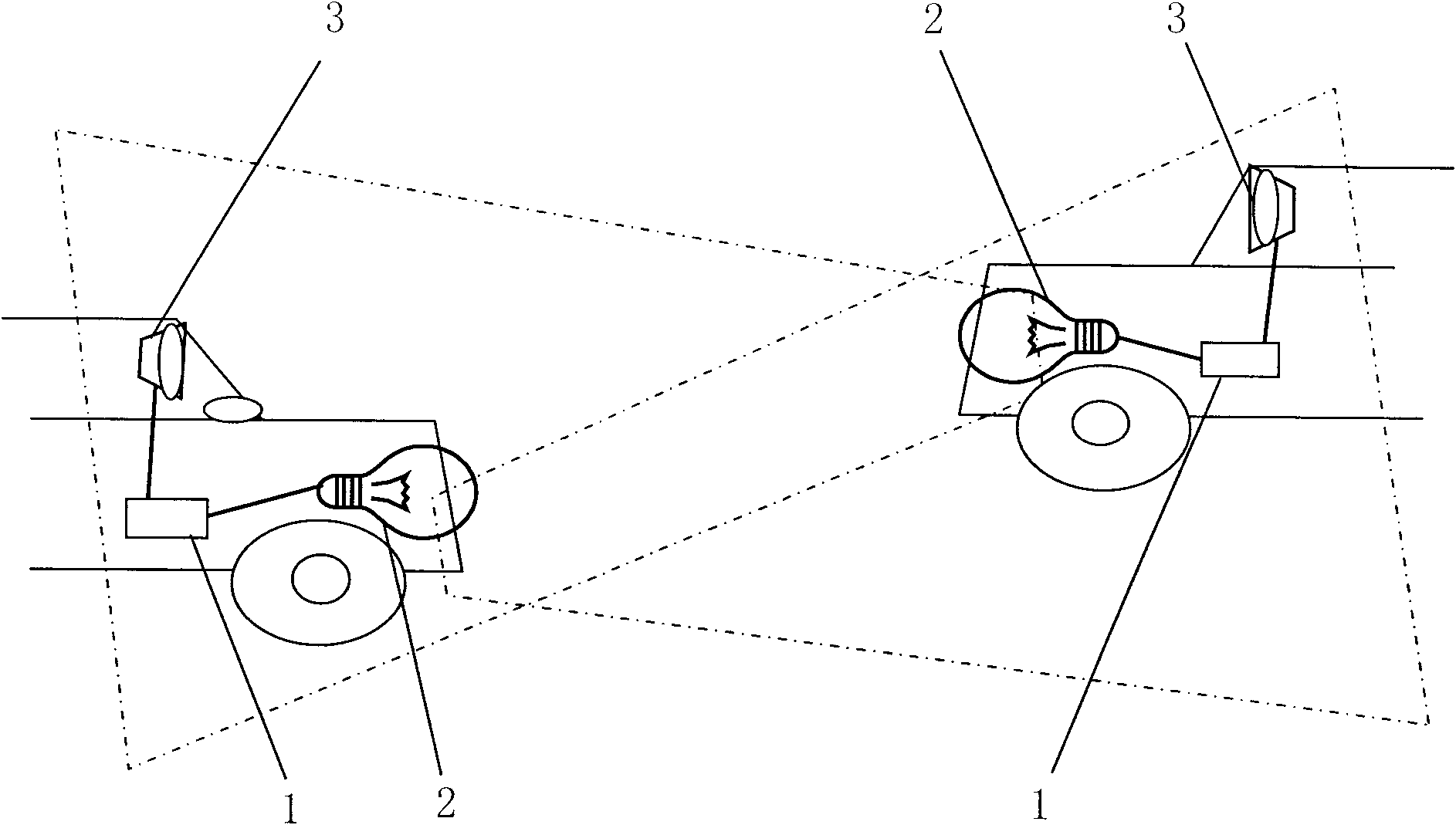
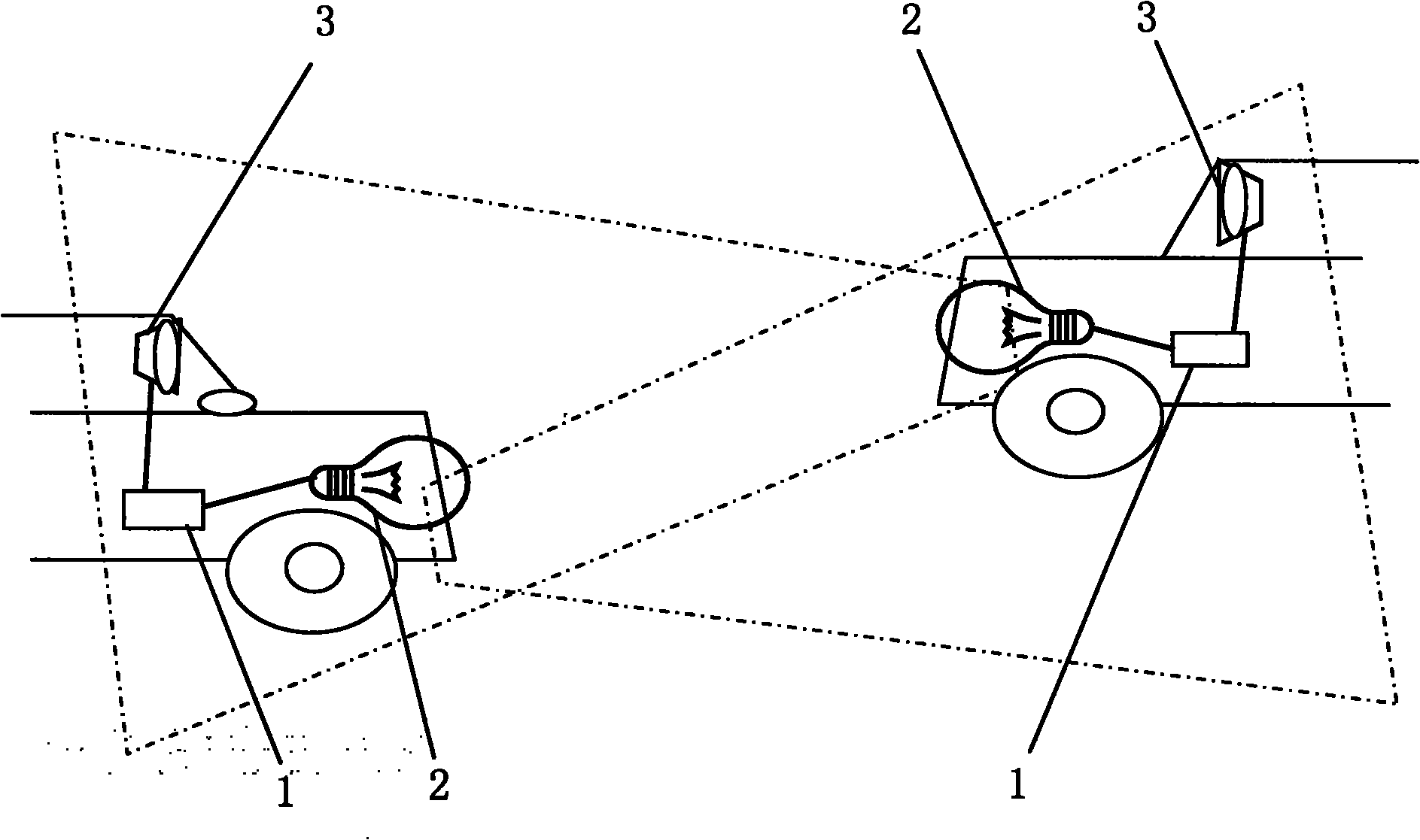
[0002] Vehicles need to turn on the lights when driving in cloudy, rainy days or at night, so that they can see the road clearly and ensure safe driving. The brightness of the lights is very high, which will affect the sight of the driver of the other vehicle when the two vehicles meet cause traffic accidents; turning off the lights will affect the driver's sight due to sudden changes in light, which is also not conducive to driving safety.
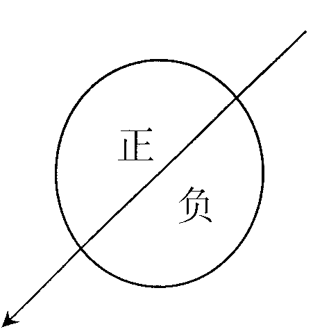
[0003] At present, in order to solve the safety problem when meeting cars, the patent 200520087657.2 is equipped with polarizers before the headlights and the windshield, and the optical axes of the two polarizers are all inclined in the same direction, and form an angle of 45 degrees with the horizontal. The light emitted by the headlights of a car is at the same angle as the windshield, so it can pass through completely without affecting the line of sight, while the light emitted by the headlights of the other party is 45 degrees on both sides, superimposed into 90 degrees, so it cannot pass through at all. It will not be dazzling; the patent seems to be able to solve the existing glare problem, but it is not practical, because after the same car is driven in the opposite direction, the polarizer is also relatively reversed at the same time, so this time it is 90 degrees. Just not visible, but just enough to see maximum brightness

Method used


Image

  • Non-glare vehicle light system
  • Non-glare vehicle light system
  • Non-glare vehicle light system

Examples


Embodiment Construction

[0011] Below in conjunction with specific embodiment, further illustrate the present invention. It should be understood that these examples are only used to illustrate the present invention and are not intended to limit the scope of the present invention. In addition, it should be understood that after reading the content of the present invention, those skilled in the art may make various changes or modifications to the present invention, and these equivalent forms also fall within the scope defined by the appended claims of the present application.

[0012] Such as figure 1 As shown, a glare-free vehicle lighting system is composed of a control unit 1, a headlight execution unit 2 and a glasses execution unit 3. The control unit 1 includes a connected electronic compass and a polarizer angle control device. The high beam execution unit 2 includes a high beam and a polarizer installed in front of the high beam, and the glasses execution unit 3 includes glasses and a polarizer...


PUM


Abstract

The invention belongs to the field of vehicle light and in particular relates to a polarized light vehicle light system. The system comprises a control unit, a front lamp execution unit and a glasses execution unit, wherein the control unit comprises an electronic compass and a polaroid angle control device which are connected with each other; the front lamp execution unit comprises a front lamp and a polaroid mounted in the front of the front lamp; the glasses execution unit comprises glasses and a polaroid mounted in the front of the glasses; the polaroids are provided with turning control devices; and the turning control devices are connected with the polaroid angle control device. The system adopts the characteristics of polarized light to realize shielding of the direct light of the reverse running vehicles, thus ensuring the drivers to be free of glare when the opposite vehicles encounter. The light from own side is identical with the bias characteristic of own lenses and the light which is reflected back can not be shielded, therefore, the drivers can see the forward road conditions clearly, thus ensuring running safety.

Description

technical field [0001] The invention belongs to the field of vehicle lighting, in particular to a polarized light vehicle lighting system. Background technique [0002] Vehicles need to turn on the lights when driving in cloudy, rainy days or at night, so that they can see the road clearly and ensure safe driving. The brightness of the lights is very high, which will affect the sight of the driver of the other vehicle when the two vehicles meet Cause traffic accident; Turning off the car light will affect the driver's line of sight because of the sudden change of light, which is also unfavorable for driving safety. [0003] At present, in order to solve the safety problem when meeting cars, the patent 200520087657.2 is equipped with polarizers before the headlights and the windshield, and the optical axes of the two polarizers are all inclined in the same direction, and form an angle of 45 degrees with the horizontal. The light emitted by the headlights of a car is at the s...

Claims


Application Information

Patent Timeline
Patent Type & Authority Applications(China)
IPC IPC(8): B60J3/06B60Q1/04G02B5/30
Inventor 励土峰
Owner 励土峰
Why Eureka
Try Eureka