

Imaging device for simulating flame
An imaging device and flame simulation technology, which is applied in lighting devices, non-electric lighting devices, portable lighting devices, etc., can solve the problems of large product size, high cost, and low flame brightness
Inactive Publication Date: 2010-10-27
ZHONGSHAN YIJIA ELECTRICAL APPLIANCE
View PDF6 Cites 1 Cited by
- Summary
- Abstract
- Description
- Claims
- Application Information
AI Technical Summary
Problems solved by technology
The problem is that this technology is applied to products with flame effects all around, the flame brightness is small, and the flame effect is not realistic
And the product size is large and the cost is high
Method used
View moreImage
Smart ImageViewing Examples

Examples
Embodiment 2
[0037] The reflector 3 is planar, and both surfaces of the reflector 3 have reflective areas; the imaging screen 4 has two, which are set opposite to the two surfaces of the reflector 3 respectively.
Embodiment 3
[0039] The reflector 3 is polygonal cylindrical, or cylindrical, or conical; the imaging screen 4 has two, and the two imaging screens 4 are arranged symmetrically around or front and back, and the two imaging screens 4 are respectively opposite to the reflector 3 set up.
Embodiment 4
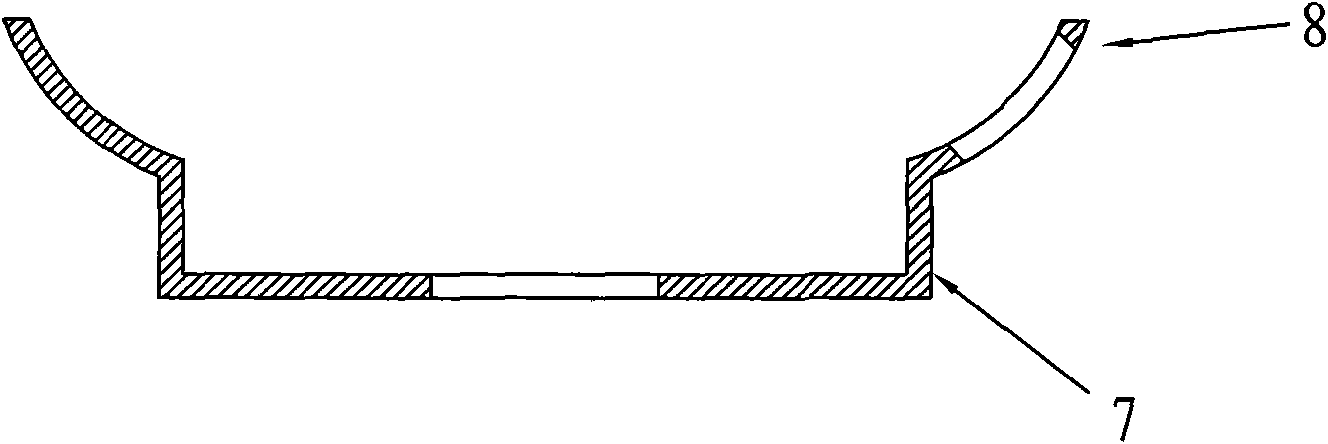
[0041] The light source 2 is located below the lower light-shielding body 52 , and the surface of the reflecting plate 3 opposite to the imaging screen 4 has an acute angle with the horizontal plane radially outside of the lower light-shielding body 52 .
Login to View More PUM
 Abstract
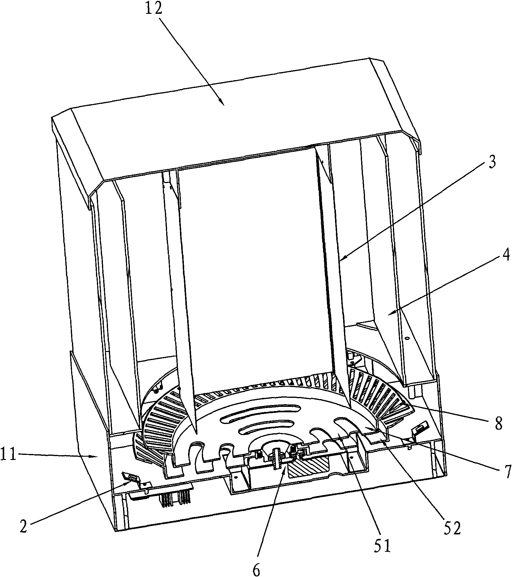
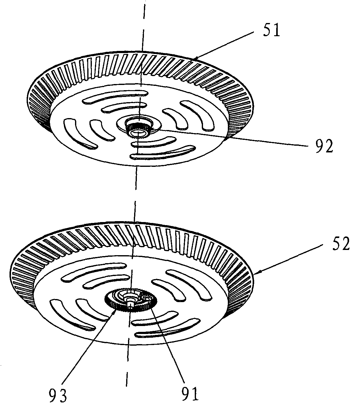
The invention relates to an imaging device for simulating flame. The imaging device comprises a shell, a light source, a reflector plate, an imaging screen, an occulter with light holes and a driving device, wherein the upper and lower occulters are arranged on the upper and lower parts of a plane parallel to the horizontal plane; a gap is reserved between the upper and lower occulters; the upper and lower occulters move relatively; the light source is positioned below the lower occulter or the light source is positioned below the outer side of the projection of the lower occulter on the horizontal plane; the reflector plate is positioned on the upper part inside the occulter; and the imaging screen is positioned above the outer side of the radial direction of the occulter. Because the imaging device for simulating the flame adopts the structure, light from the light source permeates the cross light holes of the upper and lower occulters, strong light permeates the cross light holes close to the light source and weaker light permeates the cross light holes far away from the light source to form stronger flame at the center position and form weaker flame at the positions on both sides of the center so as to present a stereoscopic effect of the flame.
Description
technical field [0001] The invention relates to a simulated flame imaging device, which can be applied to electric fireplaces, electric heaters, air heaters, induction cookers and other products requiring flame effects. Background technique [0002] Current existing technology, Chinese patent ZL200820112667.0, name of invention: a flame simulation device for an electric fireplace, which includes a light source, a reflector, an imaging screen, a light-shielding body with a light-transmitting hole, and a simulation of the front position of the casing cavity The fuel bed, the light-shielding body with light-transmitting holes is placed between the reflector and the imaging screen, the light-shielding body is cylindrical; the light-shielding body is installed on a synchronous rotating device, and the synchronous rotating device is installed on the bracket in the casing, There is a flame-shaped reflection area on the reflector; the shading body and the reflector form an acute ang...
Claims
Login to View More Application Information
Patent Timeline
 IPC IPC(8): F21S10/04F21V17/00F21V19/00F21V13/00F21V1/02F21V7/00
CPCF24C7/004
Inventor陈力
OwnerZHONGSHAN YIJIA ELECTRICAL APPLIANCE