Method and device for jointing display screens

A splicing display and screen technology, which is applied in the field of splicing screen systems, can solve problems such as increasing the number of splicing screen systems and improving performance barriers, and achieve the effect of reducing quality and small time difference

Active Publication Date: 2010-10-27
ZHE JIANG PEARMAIN ELECTRONICS
View PDF7 Cites 9 Cited by
  • Summary
  • Abstract
  • Description
  • Claims
  • Application Information

AI Technical Summary

Problems solved by technology

[0002] At present, LCD splicing screens used to expand the area of ​​displayed images or increase the displayed content are gradually favored by users for their advantages such as high definition, wide viewing angle, high brightness, and long life. It is widely used in the fields of conference TV and advertising display, but the current splicing screen system uses data replication and distribution to build the system. Using this method will be affected by factors such as the signal quality and bandwidth of the data distributor, and the splicing screen cannot be integrated. The number of splicing screen systems has increased to a large number, which has caused obstacles to the further improvement of the performance of the splicing screen system, such as figure 1 shown
So far, there have been no public reports that there is a good solution to further expand the number of display screens in the splicing screen system

Method used


Image

  • Method and device for jointing display screens
  • Method and device for jointing display screens
  • Method and device for jointing display screens

Examples


Embodiment 1

[0020] Embodiment 1: the present invention is further described below in conjunction with specific embodiment, but protection scope of the present invention is not limited to this:

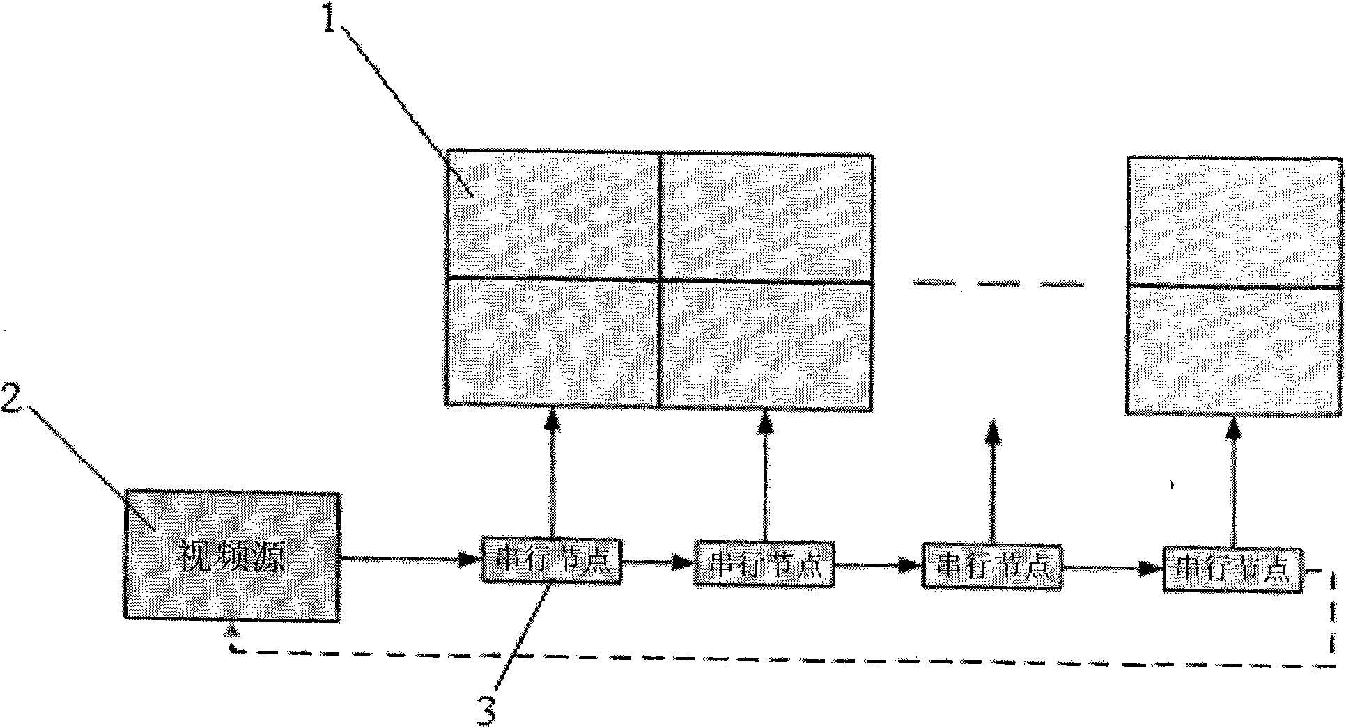
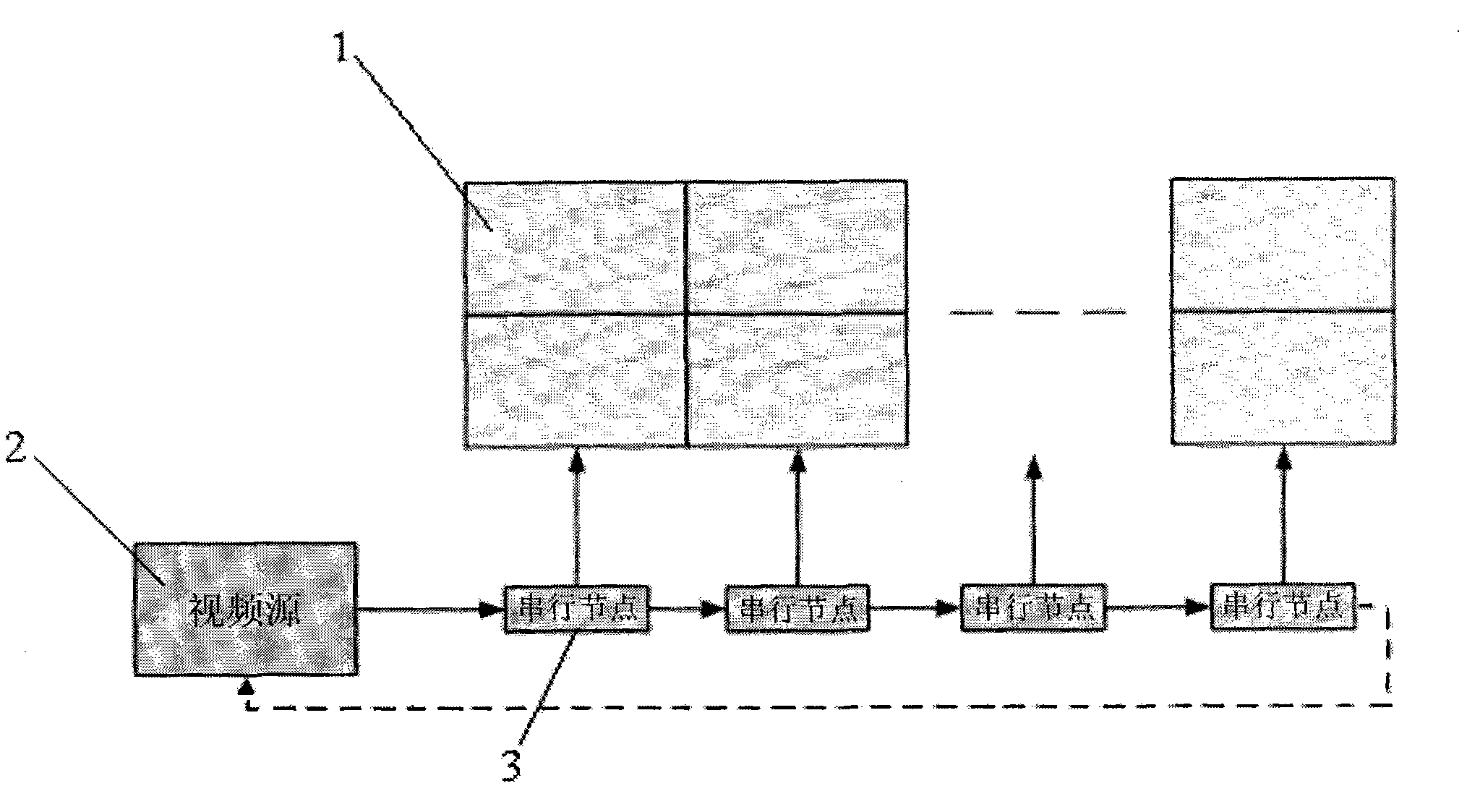
[0021] A device for splicing display screens, such as figure 2 As shown, it consists of a video source transmitter 2, a serial data bus, 16 display nodes, and 16 digital displays 1, wherein: the video source transmitter is connected to the serial data bus, and each display node is set on the serial data bus Each display node is connected to its corresponding digital display; the serial node is a video processing board 3, and each digital display of the splicing screen is connected to a board 3, and the board 3 is configured for digital According to the needs of the system, the number of screens can be arbitrarily increased by adding a plurality of processing boards 3 according to the content that the display screen needs to display, so that the entire splicing screen can display the required imag...

Embodiment 2

[0031] Embodiment 2: The difference between this embodiment and Embodiment 1 is that the data bus can be designed as a closed loop. In the closed loop situation, the video data will eventually return to the sending end, and the video source transmitter can be set at any position on the bus. Such as figure 2 Shown by the dotted line.


PUM


Abstract

The invention relates to a jointed screen system, in particular to a method and a device for jointing display screens. The method forms a serial bus of video data and makes the display screens connected with the bus in series. The data bandwidth of the serial bus does not increase with the increase in the number of the display screens, so the system may comprise an almost infinite number of screens. Thus, a problem of the prior is solved successfully. The method and the device have the advantages of allowing an infinite number of screens to be added in the system without increasing the load of the system nor reducing the quality of video frequency, and making the time differences between the arrivals of video data at the screens extremely small at the same time. When the method is used, the problem of limited number of screens of the jointed screen system is solved, so that the jointed screen system has a larger display area and more display contents.

Description

technical field [0001] The invention relates to a splicing screen system, in particular to a method and device for splicing display screens. Background technique [0002] At present, LCD splicing screens used to expand the area of ​​displayed images or increase the displayed content are gradually favored by users for their advantages such as high definition, wide viewing angle, high brightness, and long life. It is widely used in the fields of conference TV and advertising display, but the current splicing screen system uses data replication and distribution to build the system. Using this method will be affected by factors such as the signal quality and bandwidth of the data distributor, and the splicing screen cannot be integrated. The number of splicing screen systems has increased to a large number, which has caused obstacles to the further improvement of the performance of the splicing screen system, such as figure 1 shown. So far, there have been no public reports th...

Claims


Application Information

Patent Timeline
Patent Type & Authority Applications(China)
IPC IPC(8): G09G5/14
Inventor 王伟平
Owner ZHE JIANG PEARMAIN ELECTRONICS
Why Eureka
Try Eureka