Self-adaptive threshold pulse amplified shaping circuit

An adaptive threshold and shaping circuit technology, applied in the circuit field, can solve problems such as AC coupler failure, pulse loss processing, and signal pulse extraction, so as to reduce the probability of false alarms and missed alarms, reduce the impact of noise interference, and reduce Effect of Small Pulse Width Measurement Errors

Inactive Publication Date: 2010-10-27
HARBIN ENG UNIV
View PDF3 Cites 14 Cited by
  • Summary
  • Abstract
  • Description
  • Claims
  • Application Information

AI Technical Summary

Problems solved by technology

First of all, reconnaissance receivers usually work in a complex electromagnetic environment. When the pulse current density is high, the AC coupler cannot complete the extraction of signal pulses. For example, when two pulses are close to each other, they will be coupled into one pulse, resulting in pulse loss. and handle errors
Secondly, since the RF signal received by the receiver has a DC offset after video detection, the DC level drifts with temperature and time, and due to the inconsistency of the receiving channel, the DC offset of the signal after each channel is also inconsistent, resulting in pulse The difference in signal amplitude is large. At the same time, due to the influence of noise, if a certain reference level is directly selected for comparison, the measured pulse width will produce large errors and delays, and even cause serious false alarms and false alarms.

Method used


Image

  • Self-adaptive threshold pulse amplified shaping circuit
  • Self-adaptive threshold pulse amplified shaping circuit
  • Self-adaptive threshold pulse amplified shaping circuit

Examples


Embodiment Construction

[0018] The present invention is described in more detail below in conjunction with accompanying drawing example:

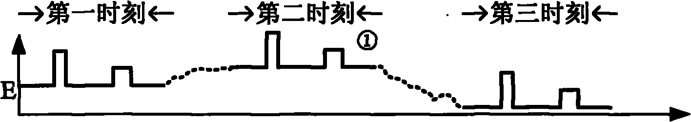
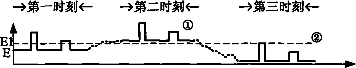
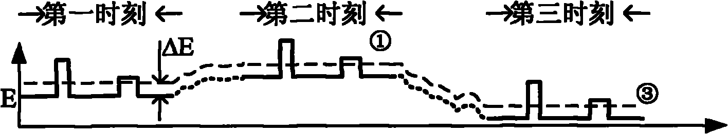
[0019] combine Figure 1-5 , figure 1 Ideally, is the video pulse envelope obtained after radio frequency detection. From the envelope signal ①, it can be seen that the DC level of the pulse envelope has a large difference in the three long time periods. At this time, the pulse cannot be recognized by the digital device, but must be compared and shaped before it can be compared with the digital device. interface. If the reference voltage of the comparator uses a fixed comparison level, such as figure 2 As shown in the fixed comparison level ②, it is easy to cause misjudgment of the pulse and have a great impact on the pulse width measurement. image 3 It is shown that the adaptive threshold is used as the reference voltage of the comparator. The comparison level ③ is obtained by adding the DC level of the pulse envelope and the adjustable voltage reference ou...


PUM


Abstract

The invention provides a self-adaptive threshold pulse amplified shaping circuit, which consists of a summing amplifier and a protective circuit thereof, a DC level extraction circuit, a reference level self-adaptive regulating circuit, and a pulse comparison shaping circuit. The self-adaptive threshold pulse amplified shaping circuit can avoid the influence on pulse envelope current drift, reduce the pulse width measurement error caused by the pulse amplitude, and reduce the influence on noise interference. Therefore, the false-alarm and miss probability is reduced.

Description

technical field [0001] The invention relates to a circuit, in particular to a circuit capable of amplifying and shaping received signals. Background technique [0002] The radio frequency signal received by the receiver is detected by the envelope detector and then outputs a video pulse signal. Due to pulse interference, thermal noise, inconsistency of the receiving channel, etc., the pulse envelope may be severely distorted (amplitude change and delay extension). When the pulse signal cannot be directly used as the measurement of the pulse parameters, but must be processed to a certain extent. The conventional processing method is: firstly, the envelope signal is coupled to the next stage through an AC coupler, and then the pulse edge is steepened through a stage voltage comparison. Usually, the reference voltage of the comparator is set to E / 2 (E is the coupled output pulse Envelope amplitude), the compared pulse signal can be handed over to the next stage for parameter m...

Claims


Application Information

Patent Timeline
Patent Type & Authority Applications(China)
IPC IPC(8): H03K5/01
Inventor 郜丽鹏赵仲恺林云李想
Owner HARBIN ENG UNIV
Why Eureka
Try Eureka