Support device of movable light fitting

A technology of a bracket device and a lamp, which is applied to electric lighting devices, lighting devices, lighting auxiliary devices and other directions carried on a rolling support body, can solve the problems of broken lamps, loose rolling wheels, falling off of lamps, etc.

Inactive Publication Date: 2010-11-03
OCEANS KING LIGHTING SCI&TECH CO LTD +1
View PDF0 Cites 1 Cited by
  • Summary
  • Abstract
  • Description
  • Claims
  • Application Information

AI Technical Summary

Problems solved by technology

The disadvantage of this structure is that after being dragged on the rails for a long time, the rolling wheels will become loose, and the shaft may even fall off from the gap, causing the lamps to fall off the rails, and even break the lamps in severe cases

Method used


Image

  • Support device of movable light fitting
  • Support device of movable light fitting
  • Support device of movable light fitting

Examples


Embodiment Construction

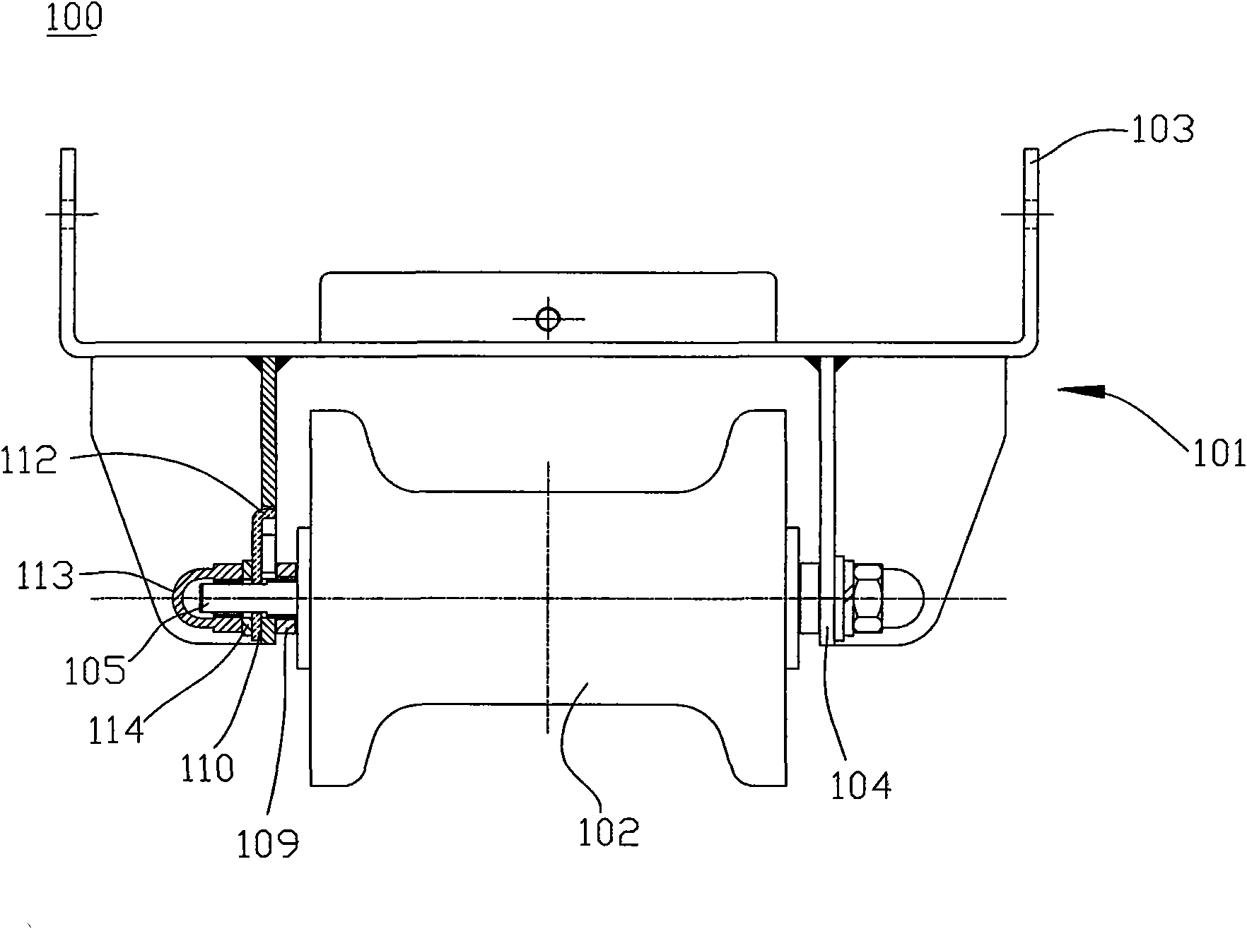
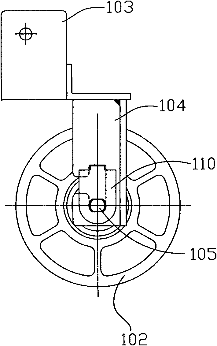
[0026] The bracket device 100 in the present invention is used to fix a lamp (not shown), and drive the lamp to move as required. The bracket device 100 is particularly suitable for working lights for railway engineering, but is not limited thereto.

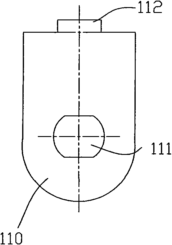
[0027] refer to Figure 1-Figure 5 , the stand device 100 mainly includes a mounting frame 101 and a pulley 102 connected to the bottom of the mounting frame. The mounting frame 101 includes a lamp mounting plate 103 on the upper part and a pulley mounting plate 104 on the lower part. Wherein the quantity of the pulley mounting plates 104 is two groups, and each group is two. The two pulley mounting plates 104 are arranged oppositely, and the pulley 102 is mounted between the two pulley mounting plates 104 through the rotating shaft 105 . Wherein the rotating shaft 105 is cylindrical, and the two ends of the rotating shaft 105 are shapes obtained by cutting the cylinder along the axial direction parallel to the rotating shaft ...


PUM


Abstract

The invention relates to a support device of a movable light fitting, comprising two pulley mounting plates arranged oppositely, a rotating shaft, a pulley and fasteners, as well as an anti-removing gaskets, wherein first gaps are arranged on the two pulley mounting plates, the rotating shaft is mounted between the two pulley mounting plates, the ends of the rotating shaft pass through the first gaps, the pulley is sleeved on the rotating shaft, each fastener is fastened at the end of the rotating shaft through the thread, and each anti-removing gasket is used for preventing the rotating shaft from removing from the first gap and is arranged between each pulley mounting plate and each fastener. The support device is provided with the anti-removing gaskets, and the first gaps are set in specific shapes, thereby the shapes of the ends of the rotating shaft are changed so that the ends of the rotating shaft are mutually acted and limited and can play the role of removal prevention.

Description

technical field [0001] The invention relates to a component of a lamp, more specifically, to a bracket device for a movable lamp. Background technique [0002] Traditional work lights for railway engineering are not equipped with pulleys for moving on rails, which is very inconvenient when the work lights need to be moved. At present, there are pulleys installed at the bottom of the support of some work lights, and the pulleys are installed on the rotating shaft, and the two ends of the rotating shaft are assembled through the gaps on the support, and then locked and fixed by elastic washers and nuts. When the bracket is pushed, the pulley slides along the track, thereby driving the work light to move. The defect of this structure is that after being dragged on the rails for a long time, the rolling wheels will become loose, and the rotating shaft may even fall off from the gap, causing the lamps to fall off the rails, and even the lamps will be broken in severe cases. Co...

Claims


Application Information

Patent Timeline
Patent Type & Authority Applications(China)
IPC IPC(8): F21L14/04F21V21/06
Inventor 周明杰周功华
Owner OCEANS KING LIGHTING SCI&TECH CO LTD
Why Eureka
Try Eureka