Spot Welding Process of Vibration-resistant Photomultiplier Tube Lead
A photomultiplier tube and spot welding technology, which is applied in the manufacture of discharge tubes/lamps, circuits, electrical components, etc.
Active Publication Date: 2012-02-08
BEIJING HAMAMATSU PHOTON TECH INC
View PDF4 Cites 0 Cited by
- Summary
- Abstract
- Description
- Claims
- Application Information
AI Technical Summary
Problems solved by technology
With the photomultiplier tube of the above-mentioned spot welding method, after the subsequent heating and cooling treatments, the lead wire will first expand and then shrink, which will cause a large stress on the welding part, and will also cause uneven force inside the tube core, causing the tube core to be crooked, deviation, even short circuit, and in the environment with strong vibration, the welding part is also easy to desolder, so that the whole pipe cannot be used normally
In addition, because there is only one solder joint between the lead wire and the parts to be welded, the only way to strengthen the welding is to increase the welding current, but this method will intensify the oxidation of the solder joint and the surrounding area of the solder joint, resulting in an increase in the dark current of the tube
Method used
View moreImage
Smart ImageViewing Examples

Examples
Embodiment Construction
Login to View More PUM
 Abstract
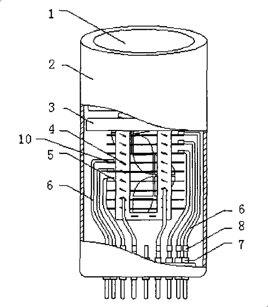
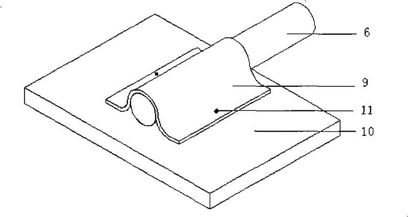
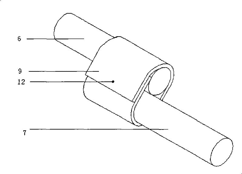
The invention relates to a spot welding process for a lead wire of a photomultiplier tube, which is particularly suitable for the spot welding process of a photomultiplier tube with high requirements for anti-vibration and impact capability. The lead wire of the photomultiplier tube is in parallel contact with the parts to be welded, and the contact point is connected by spot welding. There are at least two solder points, and then a layer of soft nickel sheet is wrapped outside the contact point. The welded parts are spot welded, or for the linear parts to be welded, the two ends of the soft nickel sheet are lapped and spot welded at the lap joint. The invention significantly strengthens the firmness of spot welding, improves the overall vibration and shock resistance of the device on the basis of effectively ensuring no increase in dark current, and broadens the application range of the product.
Description
technical field [0001] The invention relates to a spot welding process used in the internal assembly of electric vacuum devices, such as the spot welding technology used in the connection between the lead wire of a photomultiplier tube and each electrode part of the tube core, and the lead wire and the stem wire, especially suitable for anti-vibration In the spot welding process of photomultiplier tubes with high impact capacity requirements. Background technique [0002] Inside the photomultiplier tube, the lead wire mainly plays the role of support, fixation and current conduction, and the lead wire is connected to the parts to be welded by spot welding. The side is spot-welded with the stem wire, and the electrons moving inside the photomultiplier tube are finally exported through the lead wire and the stem. The firmness of the spot welding between the lead wire and the parts to be welded directly affects the anti-vibration ability of the photomultiplier tube, and the f...
Claims
Login to View More Application Information
Patent Timeline
 Patent Type & Authority Patents(China)
IPC IPC(8): H01J9/02
Inventor 段鸿滨赵建荣司永辉
Owner BEIJING HAMAMATSU PHOTON TECH INC
Features
- R&D
- Intellectual Property
- Life Sciences
- Materials
- Tech Scout
- Unparalleled Data Quality
- Higher Quality Content
- 60% Fewer Hallucinations
Learn More Browse by: Latest US Patents, China's latest patents, Technical Efficacy Thesaurus, Application Domain, Technology Topic, Popular Technical Reports.
© 2025 PatSnap. All rights reserved.Legal|Privacy policy|Modern Slavery Act Transparency Statement|Sitemap|About US| Contact US: help@patsnap.com