Spot welding technology of vibration-proof photomultiplier lead

A photomultiplier tube and spot welding technology, which is applied in the manufacture of discharge tubes/lamps, circuits, electrical components, etc., can solve problems such as the failure of the tube to be used normally, the increase of the dark current of the tube, and the easy desoldering of the welding part.

Active Publication Date: 2010-11-03
BEIJING HAMAMATSU PHOTON TECH INC
View PDF0 Cites 7 Cited by
  • Summary
  • Abstract
  • Description
  • Claims
  • Application Information

AI Technical Summary

Problems solved by technology

With the photomultiplier tube of the above-mentioned spot welding method, after the subsequent heating and cooling treatments, the lead wire will first expand and then shrink, which will cause a large stress on the welding part, and will also cause uneven force inside the tube core, causing the tube core to be crooked, deviation, even short circuit, and in the environment with strong vibration, the welding part is also easy to desolder, so that the whole pipe cannot be used normally
In addition, because there is only one solder joint between the lead wire and the parts to be welded, the only way to strengthen the welding is to increase the welding current, but this method will intensify the oxidation of the solder joint and the surrounding area of ​​the solder joint, resulting in an increase in the dark current of the tube

Method used


Image

  • Spot welding technology of vibration-proof photomultiplier lead
  • Spot welding technology of vibration-proof photomultiplier lead
  • Spot welding technology of vibration-proof photomultiplier lead

Examples


Embodiment Construction

[0009] Embodiments of the present invention will be described in detail below in conjunction with the accompanying drawings.

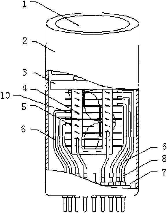
[0010] figure 1 It is a schematic diagram of the composition of the photomultiplier tube, including photocathode 1, tube shell 2, focusing system 3, tube core 4, lead wire and spot welding of each electrode part of the tube core 5, lead wire 6, photomultiplier core column wire 7, lead wire The spot welding place 8 with the stem wire and each electrode part 10 of the tube core.

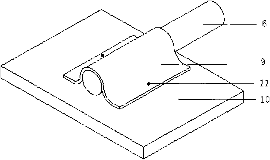
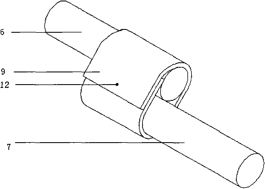
[0011] figure 2 is true figure 1 A further schematic diagram of the spot welding point 5 between the middle lead wire and each electrode part of the tube core, the lead wire 6 is in parallel contact with each electrode part 10 of the tube core, and two solder points are spot welded at the contact point, and the distance between the two solder points is 0.5 mm to 1.5 mm In between, wrap a layer of soft nickel sheet 9 outside the contact afterwards, the width of the soft nick...


PUM

PropertyMeasurementUnit
Spacingaaaaaaaaaa

Abstract

The invention relates to a spot welding technology of a photomultiplier lead, particularly adapts to the photomultiplier spot welding technology with high demands for vibration-proof ability and shock resistance. The technology is as follows: the photomultiplier lead contacts with a part to be welded in a parallel manner, spot welding is adopted at the contact site for connection, welding spots are at least two, then a soft nickel plate is covered outside the contact site, and finally spot welding is performed to the soft nickel plate and the part to be welded, or the both ends of the soft nickel plate are lapped and spot welding is performed at the lapping site. By using the spot welding technology, the fastness of spot welding is significantly increased, the vibration-proof ability and shock resistance of the entire device can be improved on the basis of effectively ensuring that dark current is not increased, and the range of application of the products is broadened.

Description

technical field [0001] The invention relates to a spot welding process used in the internal assembly of electric vacuum devices, such as the spot welding technology used in the connection between the lead wire of a photomultiplier tube and each electrode part of the tube core, and the lead wire and the stem wire, especially suitable for anti-vibration In the spot welding process of photomultiplier tubes with high impact capacity requirements. Background technique [0002] Inside the photomultiplier tube, the lead wire mainly plays the role of support, fixation and current conduction, and the lead wire is connected to the parts to be welded by spot welding. The side is spot-welded with the stem wire, and the electrons moving inside the photomultiplier tube are finally exported through the lead wire and the stem. The firmness of the spot welding between the lead wire and the parts to be welded directly affects the anti-vibration ability of the photomultiplier tube, and the fi...

Claims


Application Information

Patent Timeline
IPC IPC(8): H01J9/02
Inventor 段鸿滨赵建荣司永辉
Owner BEIJING HAMAMATSU PHOTON TECH INC
Why Eureka
Try Eureka