Communication device, cavity filter, resonating tube and manufacturing method thereof

A cavity filter and resonant tube technology, which is applied in the field of filters, can solve the problems of high cost of Invar materials and achieve the effects of low cost, cost saving and equipment cost reduction

Active Publication Date: 2014-01-08
ANHUI TATFOOK M&E TECH
View PDF6 Cites 0 Cited by
  • Summary
  • Abstract
  • Description
  • Claims
  • Application Information

AI Technical Summary

Problems solved by technology

[0005] In order to solve the problem in the prior art that the cost of using Invar materials for filters is very high, the present invention uses quartz glass materials with a low linear expansion coefficient to manufacture resonant tubes, and also provides cavity filters and communication equipment with the resonant tubes

Method used


Image

  • Communication device, cavity filter, resonating tube and manufacturing method thereof
  • Communication device, cavity filter, resonating tube and manufacturing method thereof
  • Communication device, cavity filter, resonating tube and manufacturing method thereof

Examples


Embodiment Construction

[0015] The following will clearly and completely describe the technical solutions in the embodiments of the present invention with reference to the accompanying drawings in the embodiments of the present invention. Obviously, the described embodiments are only some, not all, embodiments of the present invention. Based on the embodiments of the present invention, all other embodiments obtained by persons of ordinary skill in the art without creative efforts fall within the protection scope of the present invention.

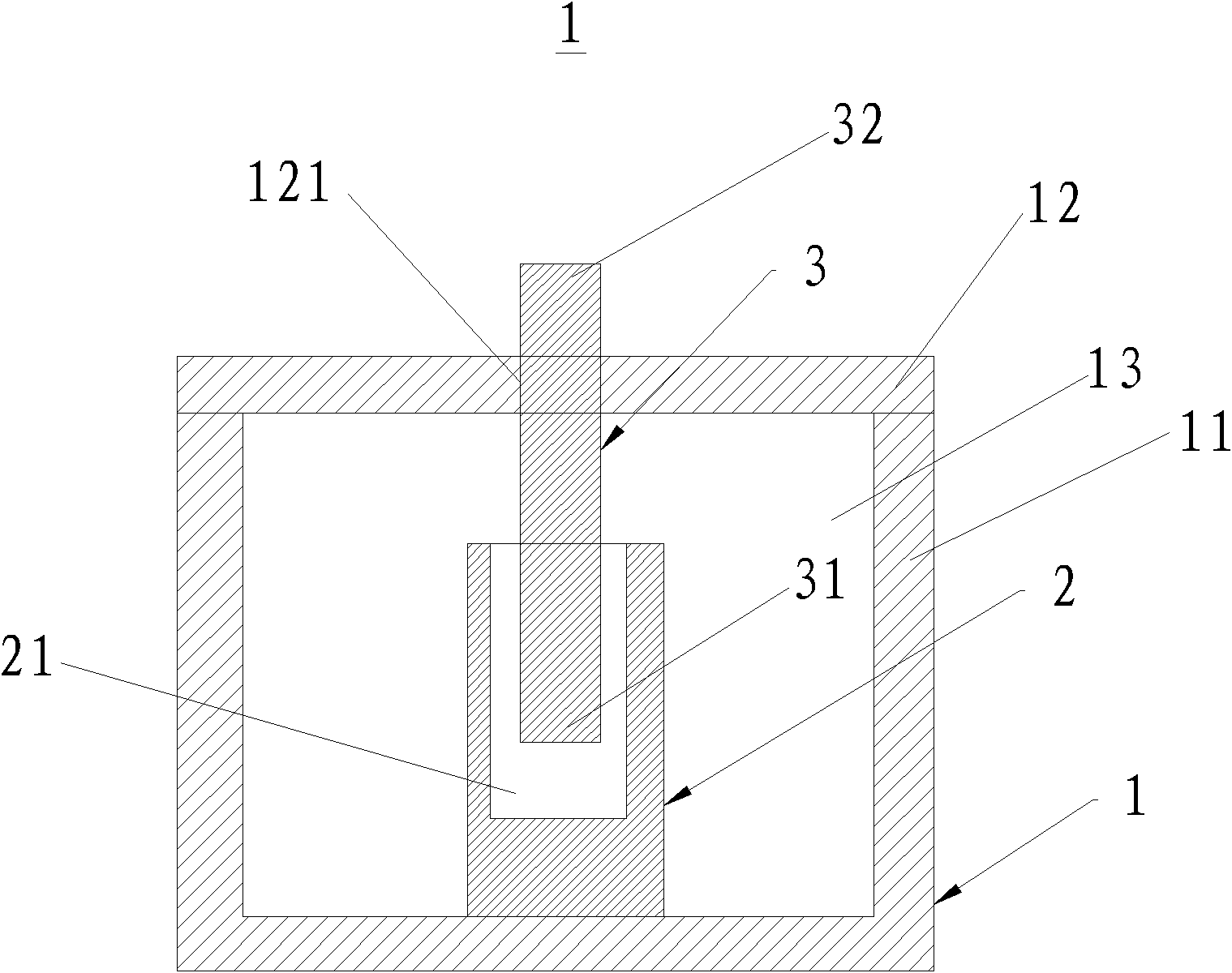
[0016] See figure 1 , figure 1 is a schematic diagram of a partial structure of a cavity filter 1 including a resonant tube 2 according to the first embodiment of the present invention.

[0017] Such as figure 1 As shown, in simple terms, the cavity filter mainly includes a cavity 1 , a resonance tube 2 , a tuning rod 3 and a cover plate 12 . Of course, the cavity filter of this embodiment also includes various other conventional components or structures. Here, ...


PUM


Abstract

A cavity filter is disclosed, wherein, the cavity filter comprises a cavity (1) and a resonance tube (2) mounted in said cavity (1), and said resonance tube (2) is made of quartz glass. Compared with the cavity filter with a traditional resonance tube made of invar, said cavity filter reduces cost, and has a better temperature drift index. A communication device, resonance tube and manufacturing method thereof are also disclosed.

Description

【Technical field】 [0001] The invention relates to the technical field of filters, in particular to a cavity filter, a resonant tube of the filter and a manufacturing method thereof, and also relates to a communication device using the cavity filter. 【Background technique】 [0002] At present, the frequency spectrum of the communication system is becoming more and more crowded, the mobile communication is developing from GSM900, 1900MHz to TD2010-2025MHz, Wimax3. The temperature drift of the cavity filter (hereinafter referred to as temperature drift) generally increases with the increase of the frequency band. At low frequencies, the temperature drift index of the filter is relatively small. The temperature drift is already very large. [0003] During the research and practice of the prior art, the inventors of the present invention found that in the prior art, the traditional free-cutting steel and brass resonant tubes have been difficult to meet the realization of the rad...

Claims


Application Information

Patent Timeline
Patent Type & Authority Patents(China)
IPC IPC(8): H01P1/207H01P11/00
CPCH01P1/207H01P1/2084H01P1/2053
Inventor 孙尚传周彦昭
Owner ANHUI TATFOOK M&E TECH
Why Eureka
Try Eureka