Communication equipment, cavity filter, resonant rod and manufacturing method thereof

A technology of cavity filter and manufacturing method, which is applied in the field of communication, can solve problems such as high cost, and achieve the effects of low cost, improved equipment performance index, and high processing efficiency

Inactive Publication Date: 2011-12-21
ANHUI TATFOOK TECH CO LTD
View PDF4 Cites 1 Cited by
  • Summary
  • Abstract
  • Description
  • Claims
  • Application Information

AI Technical Summary

Problems solved by technology

[0005] In order to solve the problem in the prior art that the cost of using Invar materials for filters is very high, the present invention uses silicon nitride materials with low linear expansion coefficients to manufacture resonant rods, and also provides cavity filters and communication devices with the resonant rods. equipment

Method used


Image

  • Communication equipment, cavity filter, resonant rod and manufacturing method thereof
  • Communication equipment, cavity filter, resonant rod and manufacturing method thereof
  • Communication equipment, cavity filter, resonant rod and manufacturing method thereof

Examples


Embodiment 1

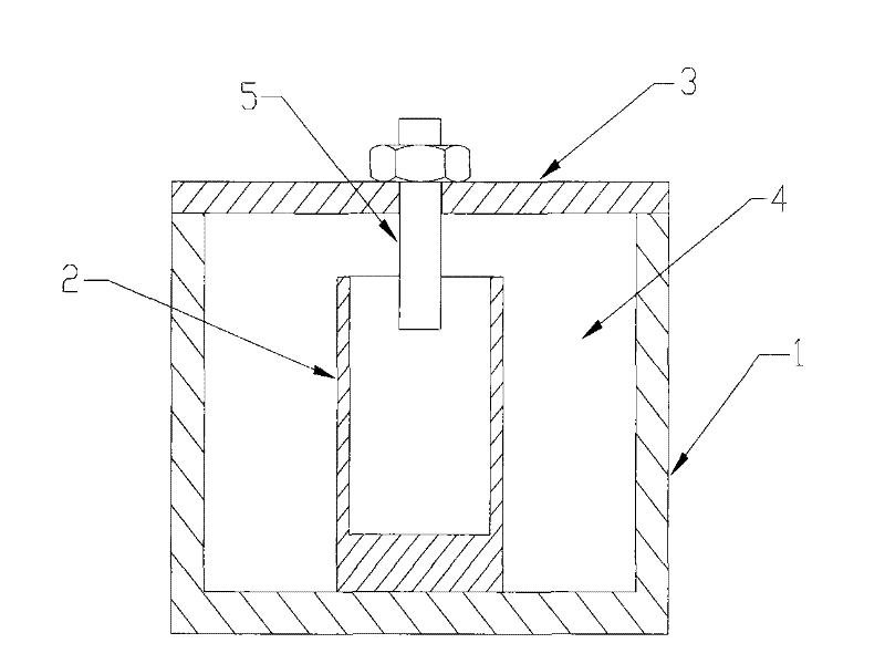
[0019] See figure 1 , figure 1 is a partial structural schematic diagram of the cavity filter 1 including the resonant rod 2 according to the first embodiment of the present invention.

[0020] like figure 1 As shown, in simple terms, the cavity filter mainly includes a cavity 1 , a resonant rod 2 and a cover plate 3 . Of course, the cavity filter of this embodiment also includes various other conventional components or structures. Here, this embodiment only describes the parts related to the invention points of this embodiment. For other specific components or structures, you can refer to the existing The conventional implementation mode does not constitute a limitation to the present invention.

[0021] In this embodiment, the cavity 1 is made of metal material, and its shape can be a square columnar cavity, a circular columnar cavity or a polygonal columnar cavity. The cover plate 3 covers the cavity 1 . The cavity 1 is covered with the cover plate 3 to form a resonant...

Embodiment 2

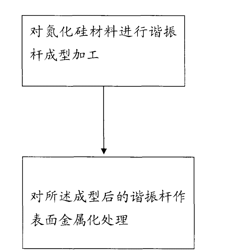
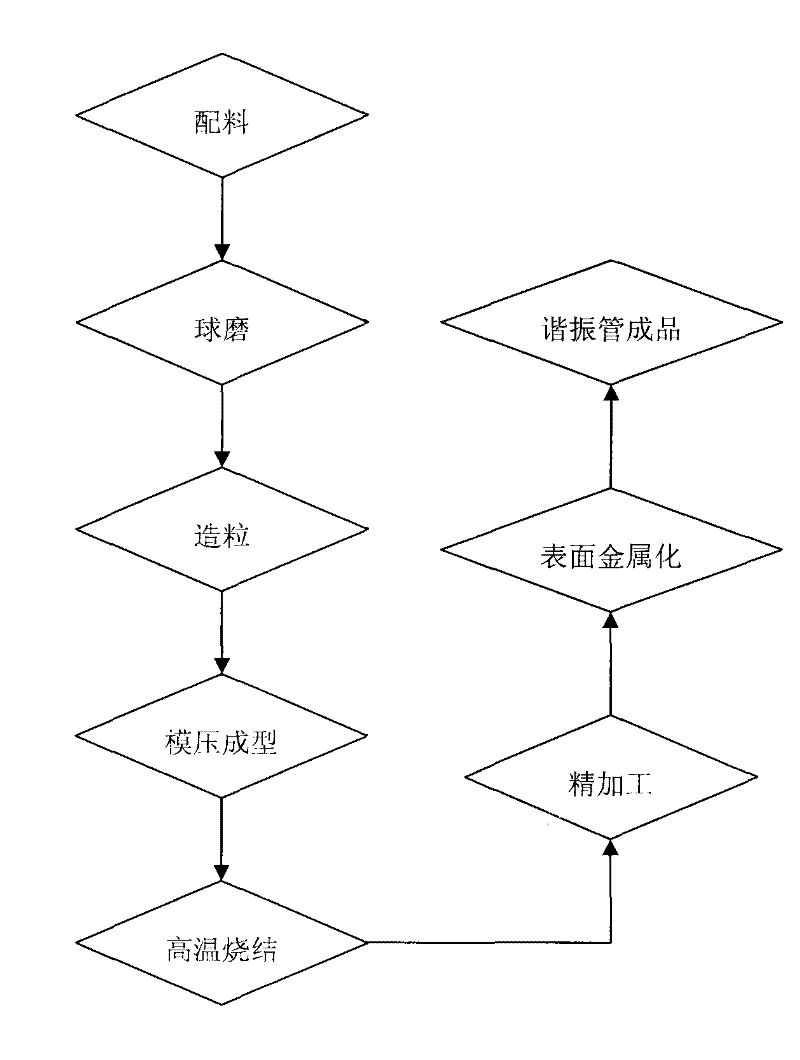
[0029] A kind of manufacturing method of resonant rod, please refer to figure 2 and image 3 , image 3 It is a simplified flowchart of a manufacturing method of the resonant rod 2 according to an embodiment of the present invention.

[0030] The general manufacturing process of the resonant rod 2 consists of two steps:

[0031] Forming and processing of resonant rods on silicon nitride materials;

[0032] Perform surface metallization treatment on the formed resonant rod.

[0033] Wherein, the process of forming the resonator rod on the silicon nitride material further includes the following steps: batching silicon nitride powder or granules as raw materials; ball milling the silicon nitride powder or granules with a ball mill to make the nitride Silicon powder or granule crushing; in order to facilitate sintering, it is usually desired to obtain ultra-fine raw material particles, but the finer the powder, the larger the specific surface area, the poorer the fluidity, an...


PUM

PropertyMeasurementUnit
densityaaaaaaaaaa

Abstract

Embodiments of the present invention disclose a cavity filter, a resonant rod and a manufacturing method thereof, wherein the resonant rod is accommodated in the cavity of the cavity filter, the surface of the resonant rod has a metal layer, and the resonant rod is made of silicon nitride material. Compared with the traditional invar material, the resonant rod made of silicon nitride has low cost, good temperature drift index and high production efficiency. In addition, an embodiment of the present invention also discloses a communication device using the cavity filter. The cavity filter is arranged in a signal transceiver circuit part of the communication device, and the resonant rod made of silicon nitride can effectively reduce the cost of the device.

Description

technical field [0001] The invention relates to the communication field, in particular to a cavity filter, a resonant rod and a manufacturing method thereof, and also relates to a communication device using the cavity filter. Background technique [0002] At present, the frequency spectrum of the communication system is becoming more and more crowded. Mobile communication is developing from GSM900, 1900MHz to TD2010-2025MHz, Wimax 3.5GHz high-frequency band, the volume of the cavity filter is getting smaller and smaller, and the structure of the base station system is more compact and flexible. The temperature drift of the cavity filter (hereinafter referred to as temperature drift) generally increases with the increase of the frequency band. At low frequencies, the temperature drift index of the filter is relatively small. The temperature drift is already very large. [0003] During the research and practice of the prior art, the inventors of the present invention found th...

Claims


Application Information

Patent Timeline
Patent Type & Authority Applications(China)
IPC IPC(8): H01P1/207H01P7/00H01P11/00
Inventor 蔡方明
Owner ANHUI TATFOOK TECH CO LTD
Why Eureka
Try Eureka