Memory control method and memory control device

A control method and control device technology, applied in the direction of instruments, data conversion, electrical digital data processing, etc., can solve problems such as unavailable triggers

Inactive Publication Date: 2010-11-10
FUJITSU LTD
View PDF3 Cites 6 Cited by
  • Summary
  • Abstract
  • Description
  • Claims
  • Application Information

AI Technical Summary

Problems solved by technology

So the problem is that it is not possible to use triggers as triggers that hold values ​​for other operations

Method used


Image

  • Memory control method and memory control device
  • Memory control method and memory control device
  • Memory control method and memory control device

Examples


Embodiment Construction

[0039] Hereinafter, embodiments of the present invention will be described with reference to the accompanying drawings.

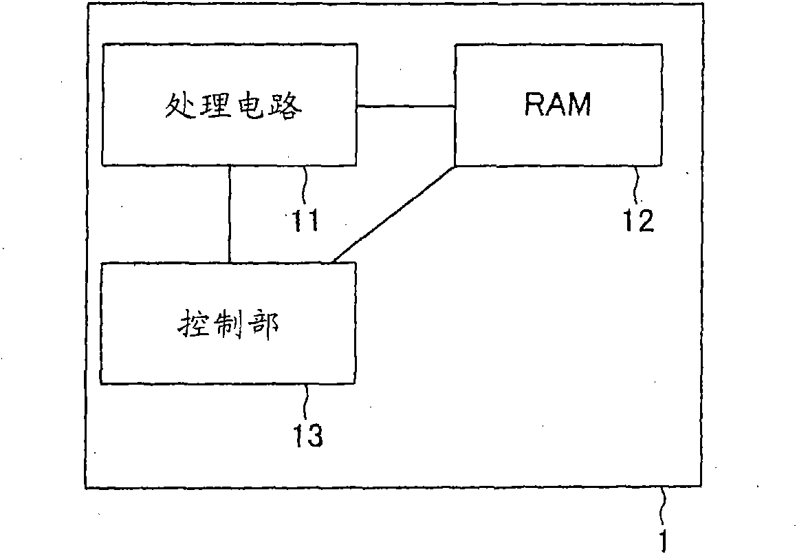
[0040] The structure of the integrated circuit of this embodiment mode will be described below. figure 1 The structure of the integrated circuit according to this embodiment is shown.

[0041] Such as figure 1 As shown, the integrated circuit 1 of this embodiment includes a processing circuit 11, a RAM 12 (memory), and a control unit 13 (memory control device). The processing circuit 11 executes predetermined processing using the RAM 12 . The RAM 12 temporarily stores data scheduled to be processed by the processing circuit 11 . The control section 13 performs first-in-first-out access control to the RAM 12 .

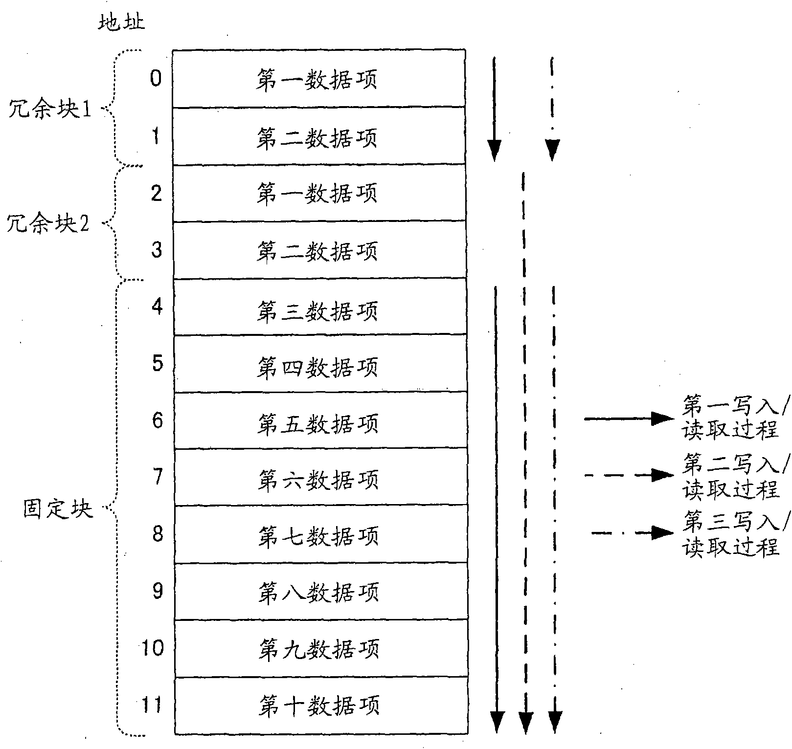
[0042] Next, the schematic structure and access control of the RAM will be described. figure 2 Show the schematic structure and access control of RAM.

[0043] Such as figure 2As shown, the RAM 12 includes memory areas represented by addre...


PUM


Abstract

A memory control method that carries out first-in first-out access control for a memory having a plurality of storage areas, including: selecting, as write positions, an address of a storage area in a storage block having at least one or more storage areas and an address of a storage area in any one of a plurality of redundant blocks that are made redundant with respect to the storage block and have at least one or more storage areas when the write positions are selected to write data to the memory; and selecting, as read positions, an address of a storage area of the storage block and an address selected by the selecting of the write position from among the addresses of a plurality of the redundant blocks when the read positions are selected to read data written by the writing of the data to the memory.

Description

technical field [0001] The present invention relates to access control of memory. Background technique [0002] FIFO (First In First Out) is a well known method of controlling RAM (Random Access Memory). Next, the FIFO access control to RAM will be described. Figure 8 FIFO access control is shown schematically. [0003] Such as Figure 8 As shown, according to the FIFO access control, initially, the first to tenth data items are written in the addresses 0 to 9 of the RAM in this order. Next, before the written data items are overwritten, the first to tenth data items are read. After that, the first to tenth data items are sequentially written. [0004] Next, the access timing of FIFO access control is described. Figure 9 The control timing of conventional RAM is shown. By the way, Figure 9 The interval of writing data to an address in the middle is 20 clocks. Also, reading data from each address takes one clock; data is read out successively. [0005] Such as Fi...

Claims


Application Information

Patent Timeline
Patent Type & Authority Applications(China)
IPC IPC(8): G06F5/12
CPCG06F5/10G06F2205/106
Inventor 丸山志津子小泉伸和
Owner FUJITSU LTD
Why Eureka
Try Eureka