Supercharge Your Innovation With Domain-Expert AI Agents!

Magnetron

A technology of magnetrons and magnets, applied in the field of magnetrons, can solve the problems of unstable operation, space limitation of high-output pulse magnetrons, difficulty in obtaining frequency stability within pulses, etc., to eliminate the difference in aggregation state, The effect of uniform magnetic flux density distribution, simple and efficient adjustment

Active Publication Date: 2013-05-22
NEW JAPAN RADIO CORP
View PDF5 Cites 0 Cited by
  • Summary
  • Abstract
  • Description
  • Claims
  • Application Information

AI Technical Summary

Problems solved by technology

When the height of the cathode body 4 is increased, the distribution range of the magnetic flux density in the direction of the Z-axis in the action space becomes wider. direction becomes larger, so that when the pulse is established, the accumulation state of the electrons is different at the center of the cathode body 4 (point O on the Z-axis) and at both ends (point A on the Z-axis), and oscillation cannot be established stably.
[0026] In particular, if the frequency of occurrence of mode hopping oscillation (moding) increases when oscillation is established, the stability of the frequency within the pulse is reduced, so that, for example, in the case of using the high-output pulse magnetron 1 as the microwave source of the linear accelerator , the reflected power from the linear accelerator becomes larger, not only cannot supply sufficient microwave power to the linear accelerator, but also the magnetron itself changes the oscillation frequency due to the influence of the reflected power, and there is a possibility that the operation becomes more unstable. this bad situation
[0027] As mentioned above, especially in the high-output pulsed magnetron that can be used as a linear accelerator, although both high output and high frequency stability are required, in order to achieve high output, the design of the cathode body is increased. The height of 4 will correspondingly reduce the frequency stability in the pulse, so it is necessary to suppress the frequency stability drop
However, since high-output pulsed magnetrons are also limited in space, there is a problem that it is difficult to obtain high intra-pulse frequency stability that satisfies the requirements.
[0028] In addition, in high-output magnetrons for linear accelerators, the magnets are often self-contained, so it is basically difficult to change the shape of the magnet (magnetic pole) and adjust the magnetic force of the pole piece attached to the magnet.

Method used


Image

  • Magnetron
  • Magnetron
  • Magnetron

Examples


Embodiment Construction

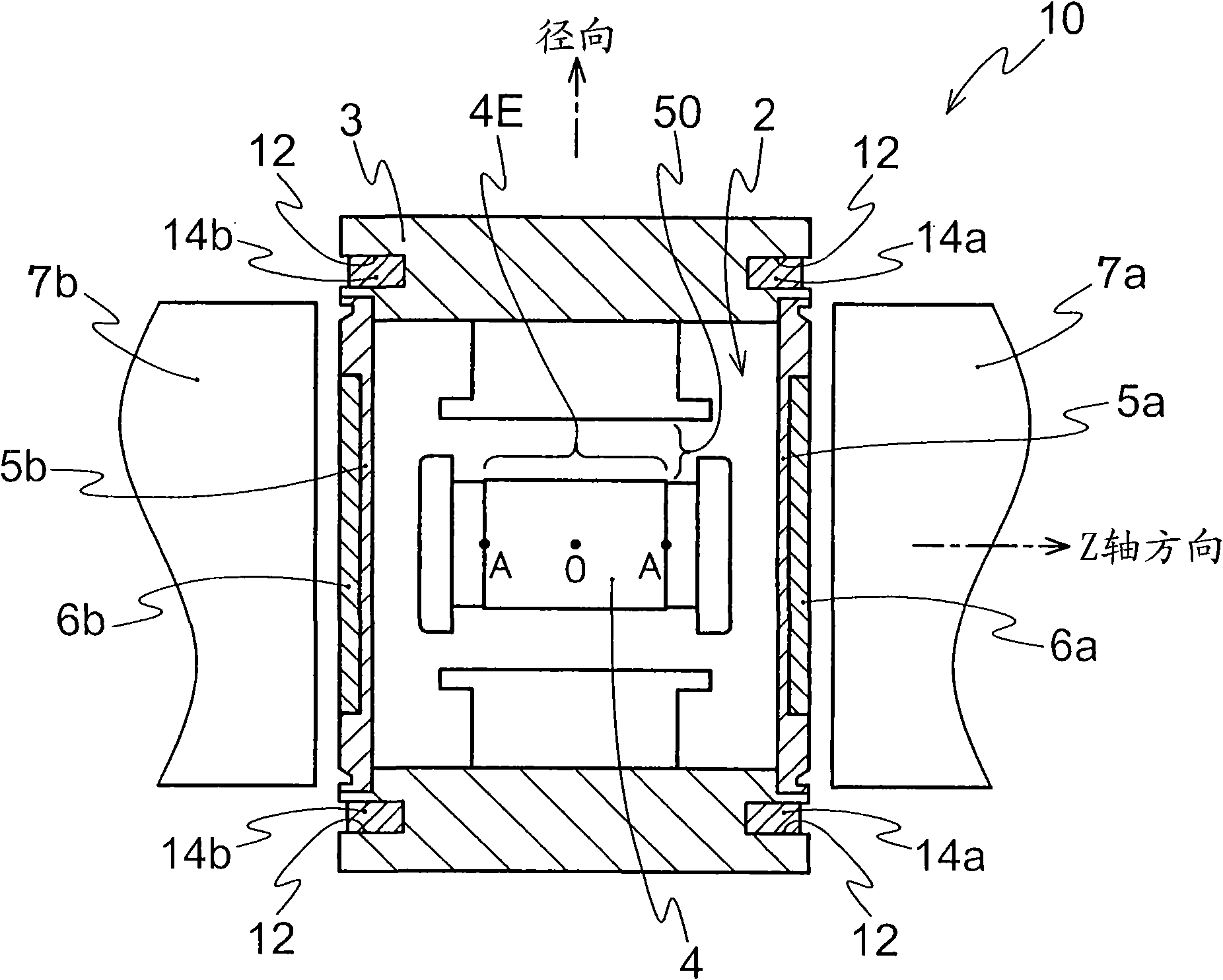
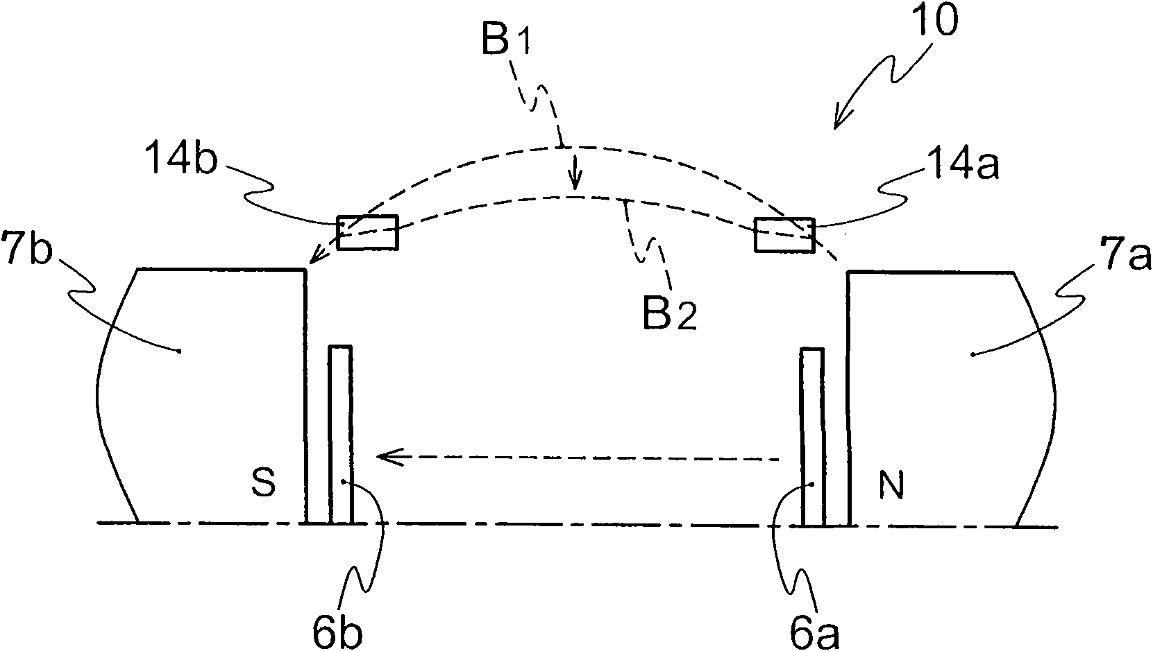
[0049] figure 1 The configuration of the magnetron as the first embodiment of the present invention is shown. In the first embodiment, the magnetron of the present invention is configured as a high-output pulse magnetron for a linear accelerator in an X-ray generator. figure 1 The magnetron 10 is, for example, a hole and slot structure, and has a cylindrical anode body 3 with a plurality of resonant cavities formed in the inner space 2. In the center of the inner space 2 of the anode body 3 (with The anode body 3 is concentrically arranged with the cathode body 4 , and the left and right openings of the internal space 2 of the anode body 3 are sealed by disk-shaped sealing members (metal) 5 a, 5 b. The outer peripheral portions of the sealing members 5 a and 5 b are sealed and fixed to the opening of the anode body 3 by welding or the like.

[0050] In addition, on the central part of the outer surface of the sealing members 5a, 5b, a disk-shaped seal is provided at a posit...


PUM


Abstract

The present invention provides a magnetron, that magnetic flux density distribution may be uniformly, simply and efficiently adjusted, and stability of pulse-inside frequency is high for high output. The magnetron (10) includes a cathodic body (4); an anodic body (3) having a plurality of resonant cavities; magnets (7a, 7b) for forming magnetic flux coaxial with a central axis namely Z axis; first magnetic bodies (6a, 6b), being of circular plate shape and arranged in an opening of an inner space of the anodic body, and the diameter of the first magnetic body is less to that of the magnet. The magnetron is provided with second annular magnetic bodies (14a, 14b) coaxial with the Z axis and arranged at a position close to the center of the Z axis relative to the first magnetic bodies and arranged on the radial external side of the first magnetic bodies independently, wherein the thickness of the second magnetic body is more than that of the first magnetic body in the Z axis direction. The second magnetic bodies are prevented from falling off by means of projections formed on seal members (5a, 5b) and the like.

Description

technical field [0001] The present invention relates to a magnetron (magnetron), in particular to a high-output pulse magnetron used to control the magnetic flux density distribution in the action space of the magnetron and improve the frequency stability in the pulse structure. Background technique [0002] Figure 11 The structure of a conventional high-output pulse magnetron is shown, and the magnetron 1 is composed of, for example, an anode body 3, a cathode body 4, sealing members (metal) 5a, 5b, magnetic bodies 6a, 6b, and magnets (magnetic poles) 7a, 7b. , wherein the anode body 3 is cylindrical and has an inner space 2 formed with a plurality of resonant cavities, the cathode body 4 is disposed in the central part of the inner space 2, and the sealing members (metal) 5a, 5b are discs ( disc) shape, they are used to close the left and right openings of the inner space 2 and close the openings at both ends of the cylindrical anode body 3, the magnetic bodies 6a, 6b ar...

Claims


Application Information

Patent Timeline
Patent Type & Authority Patents(China)
IPC IPC(8): H01J25/50
Inventor 宫本洋之梅田昭则
Owner NEW JAPAN RADIO CORP
Features
  • R&D
  • Intellectual Property
  • Life Sciences
  • Materials
  • Tech Scout
  • Unparalleled Data Quality
  • Higher Quality Content
  • 60% Fewer Hallucinations
Learn More