Supercharge Your Innovation With Domain-Expert AI Agents!

Device and method for realizing multi-permeability continuously changing toroidal core inductance

A technology of toroidal cores and toroidal inductors, used in the manufacture of inductors/transformers/magnets, circuits, electrical components, etc., can solve the problem of uneven magnetic flux density distribution, and achieve the effect of uniform magnetic flux density distribution

Active Publication Date: 2018-11-27
TIANJIN UNIV
View PDF4 Cites 0 Cited by
  • Summary
  • Abstract
  • Description
  • Claims
  • Application Information

AI Technical Summary

Problems solved by technology

[0006] The present invention is aimed at the present situation that the single magnetic permeability characteristic of commercial ring inductors leads to the uneven distribution of magnetic flux density inside and outside the magnetic ring, and proposes to use the gradient temperature field (that is, let the inside and outside of the entire magnetic ring experience different sintering temperatures) to realize A device and method for continuously changing toroidal core inductance with multi-permeability, so as to realize uniform magnetic flux density inside and outside the inductance, improve energy flow density of devices, and reduce power loss

Method used


Image

  • Device and method for realizing multi-permeability continuously changing toroidal core inductance
  • Device and method for realizing multi-permeability continuously changing toroidal core inductance
  • Device and method for realizing multi-permeability continuously changing toroidal core inductance

Examples


Embodiment 1

[0045] Utilize the clamp device prepared in the specific embodiment, operate as follows:

[0046] (a) 2g of nickel-zinc-copper ferrite powder and 0.2g of polyvinyl alcohol (PVA) solution with a mass fraction of 5% were mixed uniformly in an agate mortar.

[0047] (b) Put the homogeneously mixed product into a mold, hold the pressure at 300MPa for 5 minutes, and press to form it. The pressed annular inductor green body 1 has an outer diameter of 20 mm, an inner diameter of 10 mm, and a thickness of 3.8 mm.

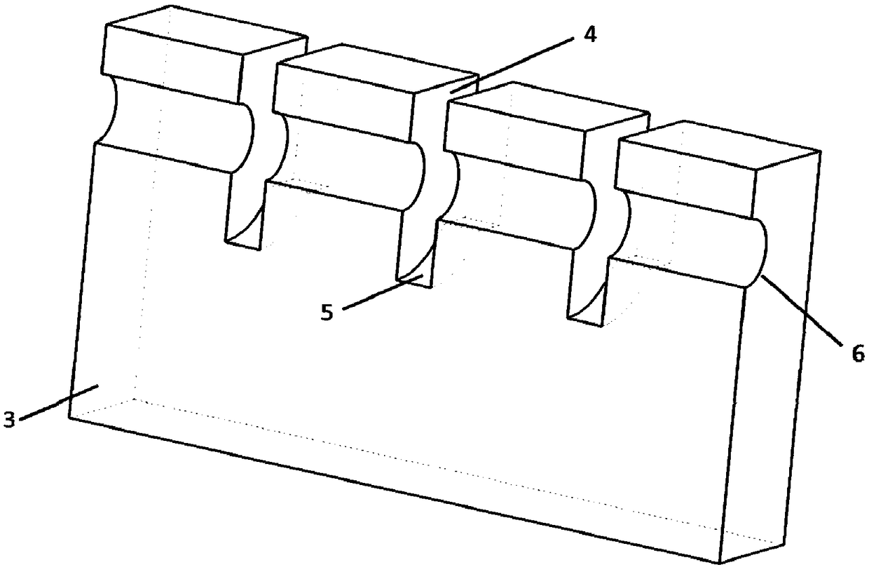
[0048](c) Put the pressed annular inductor green body 1 on the device of the present invention that can form a gradient temperature distribution for sintering, put the device in a tube furnace, and then pass air into the condensation pipe 2, and the ventilation flow rate is 12L / min, sintering at 1050°C for 2 hours.

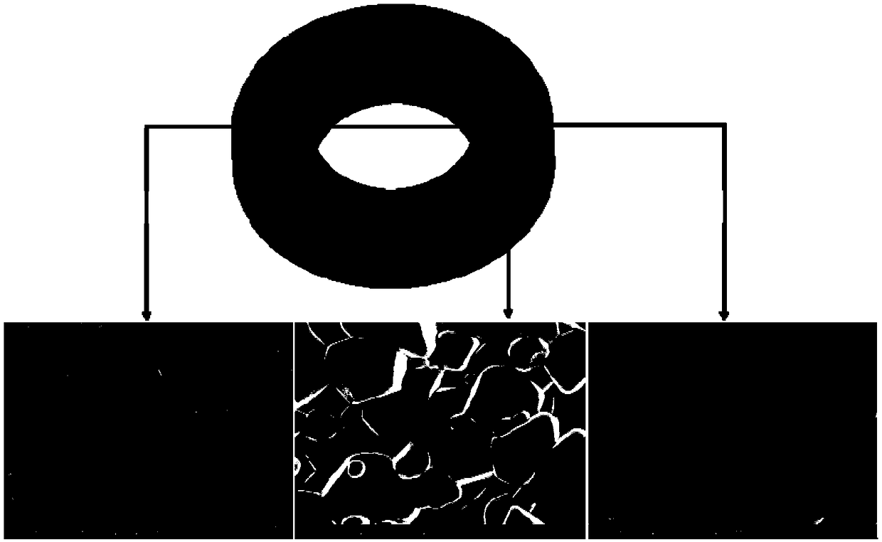
[0049] (d) The sample is cooled with the furnace, and taken out for SEM testing to observe the grain size along the radial direction of the magnetic ring. I...

Embodiment 2

[0051] Utilize the clamp device prepared in the specific embodiment, operate as follows:

[0052] (a) Take 2g of nickel-zinc-copper ferrite powder and 0.3g of polyvinyl alcohol (PVA) solution with a mass fraction of 6% and mix them uniformly in an agate mortar.

[0053] (b) Put the uniformly mixed product into a mold, hold the pressure at 400 MPa for 4 minutes, and press to form it. The pressed annular inductor green body 1 has an outer diameter of 20 mm, an inner diameter of 10 mm, and a thickness of 3.7 mm.

[0054] (c) Put the pressed annular inductor green body 1 on the device of the present invention capable of forming a gradient temperature distribution for sintering, put the device in a tube furnace, and then feed water into the condensation pipe 2 at a flow rate of 100ml / min, sintering at 1000°C for 2 hours.

[0055] (d) The sample is cooled with the furnace, and taken out for SEM testing to observe the grain size along the radial direction of the magnetic ring. It ...

Embodiment 3

[0057] Utilize the clamp device prepared in the specific embodiment, operate as follows:

[0058] (a) 2g of nickel-zinc-copper ferrite powder and 0.4g of polyvinyl alcohol (PVA) solution with a mass fraction of 10% were mixed uniformly in an agate mortar.

[0059] (b) Put the uniformly mixed product into a mold, hold the pressure at 500 MPa for 3 minutes, and press to form it. The pressed annular inductor green body 1 has an outer diameter of 20 mm, an inner diameter of 10 mm, and a thickness of 3.5 mm.

[0060] (c) Put the pressed annular inductor green body 1 on the device of the present invention capable of forming a gradient temperature distribution for sintering, put the device in a tube furnace, and then feed water into the condensation pipe 2 at a flow rate of 90ml / min, sintering at 950°C for 2 hours.

[0061] (d) The sample is cooled with the furnace, and taken out for SEM testing to observe the grain size along the radial direction of the magnetic ring. It is found...


PUM

PropertyMeasurementUnit
thicknessaaaaaaaaaa
thicknessaaaaaaaaaa
thicknessaaaaaaaaaa

Abstract

The invention discloses a device and method for achieving an annular magnetic core inductor with multi-magnetic conductivity continuously changing. The device comprises a condensation pipe and a fixture, wherein rectangular grooves are formed in the fixture, an arc groove is formed in bottom surface of each rectangular groove and is concentric to an annular inductor blank, penetrating round holes are formed in two end surfaces, perpendicular to the grooves, of the fixture, the circle centers of the round holes and the circle centers of the arc grooves are arranged on the same straight line, and the condensation pipe penetrates through the round holes of the fixture and penetrates through the whole fixture. The method comprises the steps of uniformly mixing a nickel-zinc-copper ferrite material and polyvinyl alcohol, placing a product in a die, and pressing by a tablet pressing machine to form the annular inductor blank; placing the pressed annular inductor blank in the arc grooves of the fixture, allowing the condensation pipe to penetrate through the fixture, placing the device loaded with the annular inductor blank in a tubular furnace, introducing a condensation medium into the condensation pipe, performing sintering in the tubular furnace, and cooling with the furnace after sintering is completed, wherein the condensation medium is water or air; and obtaining the annular magnetic core inductor of which the grain sizes at an inner side and an outer side or a ring are changed and the magnetic conductivity distribution is continuously changed.

Description

technical field [0001] The invention relates to a device and method for realizing multi-permeability continuously changing ring magnetic core inductance, specifically, it is a method for sintering ring magnetic core inductors through the gradient difference of temperature field, and then realizing the difference in magnetic permeability of ring magnetic core inductance , that is, to achieve the purpose of sex control through temperature control, which belongs to the field of electronic component manufacturing. Background technique [0002] As an indispensable component in high-frequency power converters and transformers, inductance devices have important applications in the power electronics industry, and ring inductors are favored as the main components of dc / dc converters. At present, the main problems of commercial ring inductors, according to the formula: [0003] [0004] Among them, B represents the magnetic flux density of the ring inductor, μ represents the magne...

Claims


Application Information

Patent Timeline
Patent Type & Authority Patents(China)
IPC IPC(8): H01F41/02
CPCH01F41/0246
Inventor 梅云辉刘君昌陆国权李欣
Owner TIANJIN UNIV
Features
  • R&D
  • Intellectual Property
  • Life Sciences
  • Materials
  • Tech Scout
  • Unparalleled Data Quality
  • Higher Quality Content
  • 60% Fewer Hallucinations
Learn More