Supercharge Your Innovation With Domain-Expert AI Agents!

Magnetic sensor device

A magnetic sensor and sensor technology, applied in measuring devices, instruments, measuring magnetic variables, etc., can solve the problem of reduced sensitivity of the magnetic sensor part, and achieve the effect of uniform distribution of magnetic flux density

Active Publication Date: 2020-03-17
MITSUBISHI ELECTRIC CORP
View PDF16 Cites 0 Cited by
  • Summary
  • Abstract
  • Description
  • Claims
  • Application Information

AI Technical Summary

Problems solved by technology

That is, in the magnetic sensor device described in Patent Document 3, the magnetic shield is formed so that the performance of the magnetic sensor does not change, and the magnetic sensor device has a magnetic sensor that is not easily affected by magnetic flux from the outside. section, however, there is a technical problem that the sensitivity of the magnetic sensor section decreases at the end in the longitudinal direction

Method used


Image

  • Magnetic sensor device
  • Magnetic sensor device
  • Magnetic sensor device

Examples


Embodiment approach 1

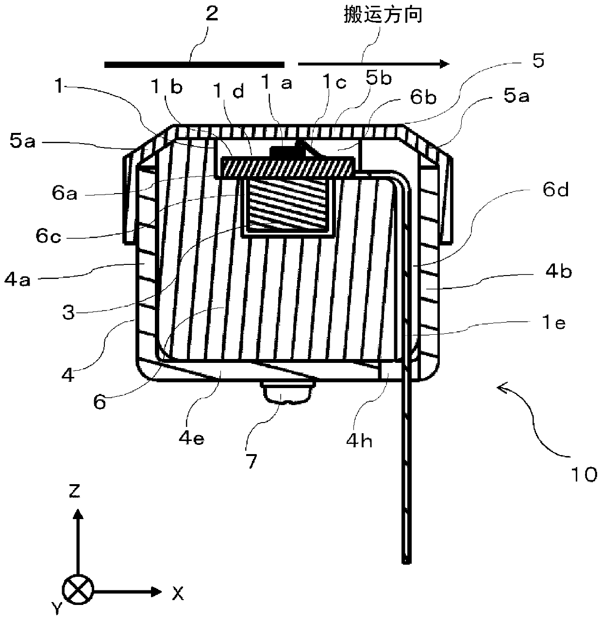
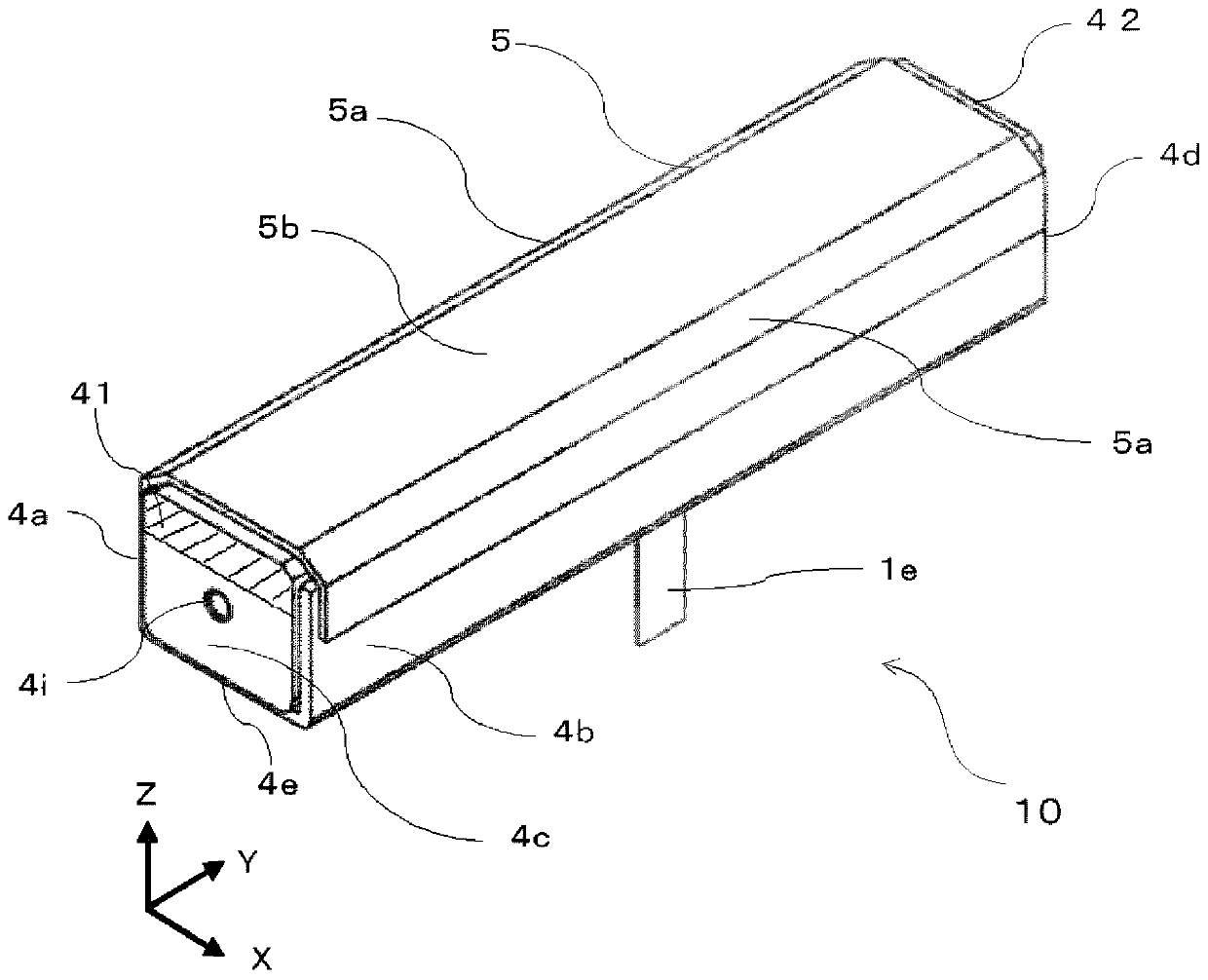
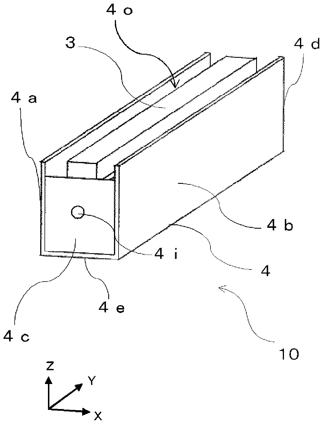
[0053] Below, use Figure 1 to Figure 7 , the magnetic sensor device 10 according to Embodiment 1 of the present invention will be described. In the drawings, the same symbols are attached to the same or equivalent structures. The magnetic sensor device 10 is a device including a magnetic sensor unit 1 including a magnet 3 , and allowing the magnetic sensor unit 1 to detect a magnetic component of a detection object 2 .

[0054] In other embodiments including Embodiment 1, the main scanning direction of the magnetic sensor device 10 is the long side direction of the magnetic sensor unit 1 , and the sub scanning direction is the short side direction. The main scanning direction intersects with the sub-scanning direction, preferably orthogonally. The main scanning direction is also referred to as the read width direction. The sub-scanning direction is also referred to as the conveyance direction. The direction perpendicular to both the main scanning direction and the sub-sca...

Embodiment approach 2

[0101] Below, use Figure 8A , 8B as well as Figure 9 , the magnetic sensor device 20 according to Embodiment 2 of the present invention will be described. Including other embodiments, in the drawings, the same or equivalent structures are denoted by the same symbols. The magnetic sensor device 20 is a device that includes a magnetic sensor unit 1 , a magnetic shield unit 4 , a housing 6 , and a cover unit 5 , and allows the magnetic sensor unit 1 to detect a magnetic component of a detection object 2 , wherein the magnetic sensor unit 1 includes a magnet 3 . The structures and functions of the magnetic sensor unit 1 , the casing 6 and the cover unit 5 are the same as those of the first embodiment.

[0102] Figure 8A and Figure 8B It is a perspective view of the magnetic sensor device 20 according to Embodiment 2, and the magnetic sensor unit 1 , the cover unit 5 , and the case 6 are omitted for easy understanding of the structure of the magnetic sensor device 20 . e...

Embodiment approach 3

[0112] use Figure 10 as well as Figure 11 , the magnetic sensor device 30 according to Embodiment 3 of the present invention will be described. Including other embodiments, in the drawings, the same or equivalent structures are denoted by the same symbols. In this embodiment, the magnetic sensor device 30 also includes the magnetic sensor unit 1, the magnetic shield unit 4, the casing 6, and the cover unit 5, and enables the magnetic sensor unit 1 to detect the magnetic component of the detection object 2. The sensor part 1 includes a magnet 3 . The structures and functions of the magnetic sensor unit 1 , the casing 6 and the cover unit 5 are the same as those of the first embodiment.

[0113] Figure 10 It is a perspective view of the magnetic sensor device 30 according to the third embodiment, and the magnetic sensor unit 1 , the cover unit 5 and the case 6 are omitted for easy understanding of the structure of the magnetic sensor device 30 . The difference from Embod...


PUM


Abstract

A magnetic sensor device (10) comprises: a magnetic sensor unit that is provided with a magnetoresistance effect element mounted on a sensor substrate extending in the lengthwise direction and a magnet (3) provided on a side of the sensor substrate opposite the magnetoresistance effect element; a case for supporting the magnetic sensor unit; a magnetic shield part (4) for covering the side surfaces and the bottom surface of the case; and a cover part for covering the upper area of the case. The magnetic shield part (4) includes an opening (4o) in the Z-axis direction from the magnetoresistanceeffect element along a conveyance path of a detection object. The opening (4o) has two lengthwise sides along the lengthwise direction, and two widthwise sides along the widthwise direction. The twolengthwise sides of the magnetic shield part (4) are closer to the detection object in the Z-axis direction than the two widthwise sides.

Description

technical field [0001] The present invention relates to a magnetic sensor device that detects a magnetic pattern formed on a paper-like medium. Background technique [0002] As a device for reading paper-like media, there is known a magnetic sensor device that includes a magnet and a magnetic sensor and that reads a magnetic pattern formed on a media such as banknotes with a magnetic component such as magnetic ink. For detection by the magnetic sensor, a magnetoresistance effect element (for example, refer to Patent Document 1, etc.), a Hall element, or the like is used. [0003] The magnetic sensor device described in Patent Document 1 includes a magnet and a magnetoresistance effect element. The magnet has magnetic poles facing one surface of the paper-like medium having a magnetic component and differing in a vertical direction perpendicular to the conveyance direction of the paper-like medium, thereby forming a cross magnetic field intersecting the object to be detected...

Claims


Application Information

Patent Timeline
Patent Type & Authority Applications(China)
IPC IPC(8): G01R33/02G01R33/09G07D7/04
CPCG07D7/04G01R33/0076G01R33/0017G01R33/091G01R33/0011G01R33/096
Inventor 尾込智和下畑贤司松井秀树吉冈贞明
Owner MITSUBISHI ELECTRIC CORP
Features
  • R&D
  • Intellectual Property
  • Life Sciences
  • Materials
  • Tech Scout
  • Unparalleled Data Quality
  • Higher Quality Content
  • 60% Fewer Hallucinations
Learn More