Supercharge Your Innovation With Domain-Expert AI Agents!

Magnetic-field-generating apparatus for magnetron sputtering

a technology of magnetron sputtering and magnetic field generation, which is applied in the direction of magnets, magnet bodies, vacuum evaporation coating, etc., can solve the problems of slow erosion of targets in the center portion, increased costs, and inability to meet the needs of target erosion, so as to improve the use efficiency of targets

Inactive Publication Date: 2015-11-26
HITACHI METALS LTD
View PDF0 Cites 0 Cited by
  • Summary
  • Abstract
  • Description
  • Claims
  • Application Information

AI Technical Summary

Benefits of technology

The present invention provides a magnetic-field-generating apparatus for magnetron sputtering that improves the use efficiency of a target by relatively accelerating erosion in a target portion opposing a center magnetic pole member. This is achieved by replacing a portion of the permanent magnets with magnet units comprising pluralities of permanent magnets magnetized in a perpendicular direction to the target surface and pluralities of permanent magnets magnetized in parallel to the target surface and arranged on both sides thereof. This reduces the vertical component of a magnetic flux density on the target surface opposing the center magnetic pole member.

Problems solved by technology

However, because this magnetic-field-generating apparatus generates a magnetic field having a lower magnetic flux density in a region opposing the center magnetic pole member than in other regions, the erosion of a target is slow in a center portion opposing the center magnetic pole member.
However, the magnetron sputtering apparatus described in JP 7-74439 B has a structure comprising permanent magnets extending outside the target (outside the outer magnetic pole) to prevent the local erosion of the target, the magnetic-field-generating apparatus is inevitably large, suffering cost increase.

Method used


Image

  • Magnetic-field-generating apparatus for magnetron sputtering
  • Magnetic-field-generating apparatus for magnetron sputtering
  • Magnetic-field-generating apparatus for magnetron sputtering

Examples


example 1

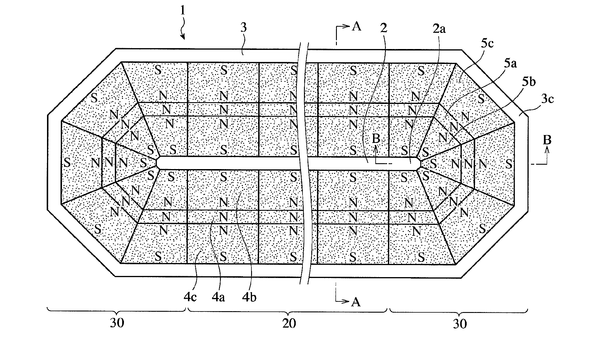
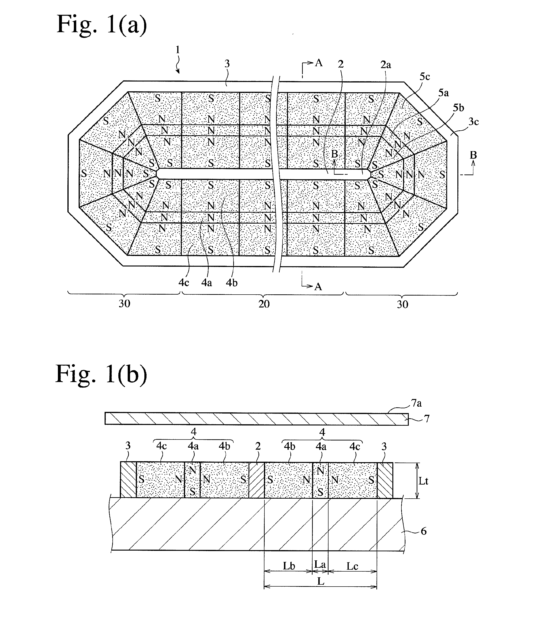
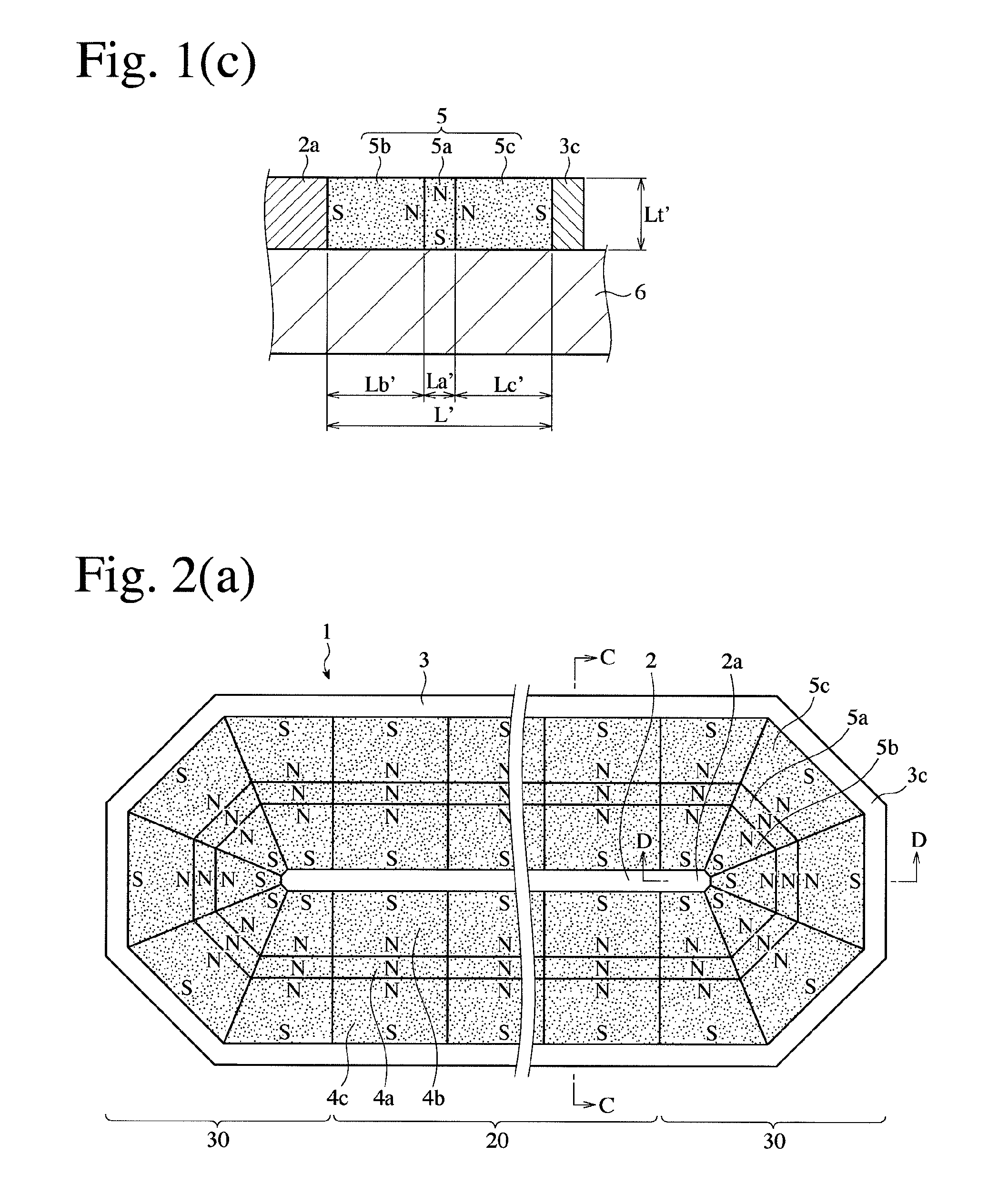
[0125]As shown in FIGS. 10(a) and 10(b), a center magnetic pole member 2 and a peripheral magnetic pole member 3 both made of ferritic stainless steel (SUS430), and permanent magnet units 4 (vertical permanent magnets 4a, and first and second horizontal permanent magnets 4b, 4c) for the straight portion and permanent magnet units 5 (vertical permanent magnets 5a, and first and second horizontal permanent magnets 5b, 5c) for the corner portions both made of a sintered ferrite magnet (NMF-12F available from Hitachi Metals, Ltd., residual magnetic flux density: about 450 mT) were arranged on a base 6 made of an Al—Mg alloy (A5052), to produce a magnetic-field-generating apparatus 1 (W=160 mm, L=70 mm, La=10 mm, Lb=30 mm, Lc=30 mm, a=10 mm, b=5 mm, and c=25 mm).


PUM

PropertyMeasurementUnit
magnetic flux densityaaaaaaaaaa
magnetic fieldaaaaaaaaaa
residual magnetic flux densityaaaaaaaaaa

Abstract

A racetrack-shaped magnetic-field-generating apparatus for magnetron sputtering comprising a straight portion and corner portions, which comprises, on a non-magnetic base, (a) a straight center magnetic pole member; (b) a peripheral magnetic pole member surrounding the center magnetic pole member; (c) pluralities of vertical permanent magnets arranged between the center magnetic pole member and the peripheral magnetic pole member, which are magnetized in a perpendicular direction to the target surface; and (d) pluralities of first and second horizontal permanent magnets arranged on both sides thereof, which are magnetized in parallel to a target surface; the magnetic poles of the first and second horizontal permanent magnets opposing the vertical permanent magnets being the same in polarity as those of the vertical permanent magnets opposing the target surface.

Description

FIELD OF THE INVENTION[0001]The present invention relates to a magnetic-field-generating apparatus assembled in a magnetron sputtering apparatus forming a thin film on a substrate surface.BACKGROUND OF THE INVENTION[0002]Sputtering is a phenomenon that atoms or molecules are projected from a target, against which an inactive material such as Ar, etc. impinges at a high speed, and that the projected atoms or molecules are attached to a substrate to form a thin film. A magnetron sputtering method uses a magnetic field in a cathode to accelerate an accumulating speed of a target material on a substrate, forming a thin film at a low temperature because of no collision of electrons to the substrate. Accordingly, the magnetron sputtering method is widely used to form thin films on substrates in the production of electronic devices such as semiconductor ICs, flat panel displays and solar cells, reflection films, etc.[0003]A magnetron sputtering apparatus comprises, in a vacuum chamber, a s...

Claims


Application Information

Patent Timeline
Patent Type & Authority Applications(United States)
IPC IPC(8): H01J37/34H01F7/02
CPCH01F7/0205H01J37/3405C23C14/35H01J37/3408H01J37/3452
Inventor KURIYAMA, YOSHIHIKO
Owner HITACHI METALS LTD
Features
  • R&D
  • Intellectual Property
  • Life Sciences
  • Materials
  • Tech Scout
  • Unparalleled Data Quality
  • Higher Quality Content
  • 60% Fewer Hallucinations
Learn More