High-gain boost converter with inductance-capacitance switching network

A boost converter and switching network technology, applied in the direction of conversion equipment without intermediate conversion to AC, can solve the problem of small output voltage gain, increased duty cycle, and input voltage drop of non-isolated DC-DC converters, etc. question

Inactive Publication Date: 2010-11-10
SOUTH CHINA UNIV OF TECH +1
View PDF6 Cites 12 Cited by
  • Summary
  • Abstract
  • Description
  • Claims
  • Application Information

AI Technical Summary

Problems solved by technology

[0003] The output voltage gain of this non-isolated DC-DC converter is small. Although a higher output voltage can be obtained by setting a larger duty cycle, the Boost power

Method used


Image

  • High-gain boost converter with inductance-capacitance switching network
  • High-gain boost converter with inductance-capacitance switching network
  • High-gain boost converter with inductance-capacitance switching network

Examples


Embodiment Construction

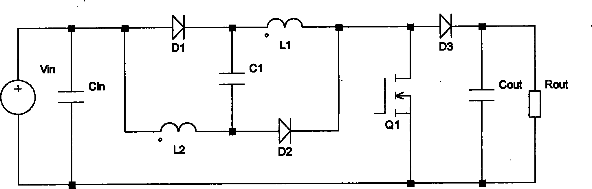
[0015] see figure 1 , the high-gain boost converter with an inductor-capacitor switching network of the present invention includes a power switch tube Q1, two Boost power inductors L1, L2, an intermediate energy storage capacitor C1, and three rectifier diodes D1, D2, D3 . The drain of Q1 is connected to one end of L1, the cathode of D2 and the anode of D3, the other end of L1 is connected to one end of C1 and the cathode of D1, one end of L2 is connected to the other end of C1 and the anode of D2, and the other end of L2 Connect to the anode of D1 and connect to the positive pole of the input power supply.

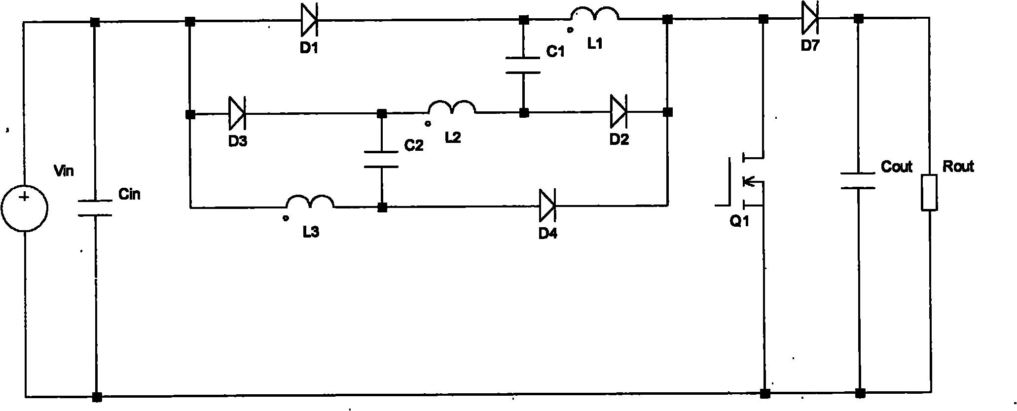
[0016] or as figure 2 As shown, the connection mode of the main power conversion circuit remains unchanged, adding an LC switch network L3, C2, and two other rectifier diodes D3, D4, this power converter can achieve three times the output voltage of the conventional Boost converter.

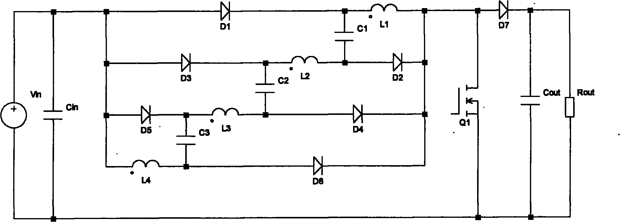
[0017] or as image 3 As shown, the connection mode of the main power conversion ci...


PUM


Abstract

The invention discloses a high-gain boost converter with an inductance-capacitance switching network, which comprises a power switching tube, two Boost power inductors, an intermediate energy storage capacitor and three rectifying diodes. The invention realizes output boosting by using the intrinsic characteristic of an LC (Latching Controller) switching network and can achieve high-gain of output voltage by combining with a Boost converter.

Description

technical field [0001] The invention relates to a non-isolated DC-DC converter, specifically a high-gain Boost (boost) converter with an LC (inductor-capacitor) switch network. Background technique [0002] A conventional Boost converter includes a power switch tube, a Boost power inductor, and a rectifier diode. The drain of the power switch tube is connected to one end of the Boost power inductor and the anode of the rectifier diode, and the other end of the Boost power inductor is connected to the positive pole of the input power supply. [0003] The output voltage gain of this non-isolated DC-DC converter is small. Although a higher output voltage can be obtained by setting a larger duty cycle, the Boost power inductor and other parasitic factors in the circuit limit the output voltage. Further improve. When the duty cycle increases to a certain range, the input voltage may even decrease instead. Therefore, the duty cycle of the conventional Boost converter cannot be ...

Claims


Application Information

Patent Timeline
IPC IPC(8): H02M3/06H02M3/07
Inventor 胡炎申张凌云李钟东谢运祥
Owner SOUTH CHINA UNIV OF TECH
Why Eureka
Try Eureka