Motor-driven control chip provided with ESD circuit

A control chip and motor control technology, which is applied to emergency protection circuit devices, electrical components, circuit devices, etc. for limiting overcurrent/overvoltage, and can solve problems such as correct signal transmission and failure of the motor speed output terminal.

Active Publication Date: 2012-11-28
AMTEK SEMICON
View PDF0 Cites 0 Cited by
  • Summary
  • Abstract
  • Description
  • Claims
  • Application Information

AI Technical Summary

Problems solved by technology

[0007] In order to improve the problem that the motor speed output terminal of the PWM control chip (that is, the FG signal terminal) cannot generate correct signals and transmit them to the control substrate, and at the same time increase the ESD protection of the PWM control chip

Method used


Image

  • Motor-driven control chip provided with ESD circuit
  • Motor-driven control chip provided with ESD circuit
  • Motor-driven control chip provided with ESD circuit

Examples


Embodiment Construction

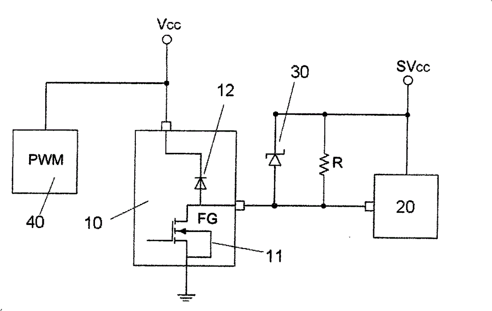
[0017] The control chip driven by the single-phase motor of the present invention is in its V CC The terminal is used for PWM control, and the motor rotation signal needs to be output from the FG pin to the control board, so that the control board can correctly control the motor. At the same time, because the voltage design between the single-phase motor drive control chip and the control board is not necessarily the same, the FG pins are designed as open drain or open collector circuits. However, the circuit structure of open drain or open collector cannot achieve ESD protection, so the ESD protection of the PWM control chip is relatively weak.

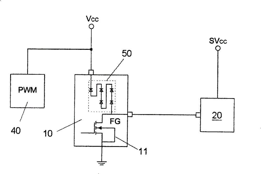
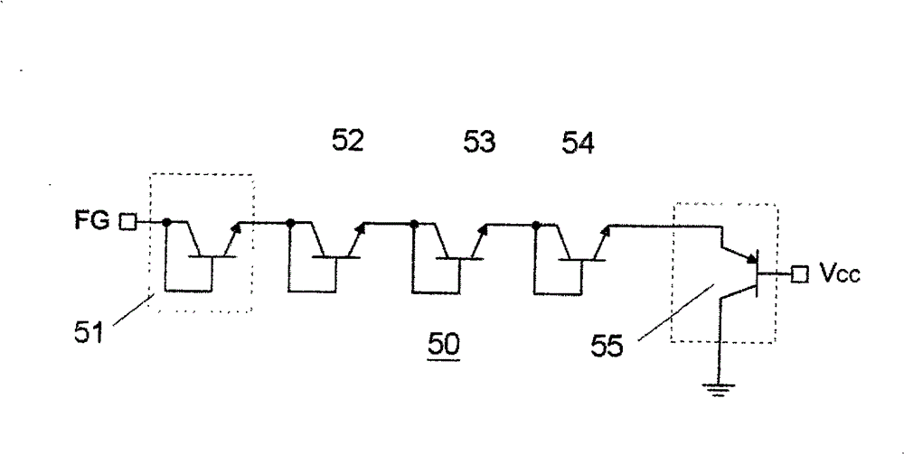
[0018] According to above-mentioned situation, the present invention is in the V of the control chip driven by single-phase motor CC An ESD (Electrostatic Discharge) circuit is arranged between the voltage terminal and the output terminal (FG) of the single-phase motor speed, such as figure 2 Shown, where the structure of the ESD ...


PUM


Abstract

The invention relates to a motor-driven control chip, comprising a voltage terminal and a motor rotating speed output terminal as well as an ESD circuit arranged between the voltage terminal and the motor rotating speed output terminal; wherein the ESD circuit is composed of at least one PNP semiconductor element and a plurality of NPN semiconductor elements, and the size of one NPN semiconductorelement in a plurality of NPN semiconductor elements is larger than the sizes of other NPN semiconductor elements.

Description

technical field [0001] The present invention relates to a motor-driven control chip (hereinafter referred to as PWM control chip), in particular to a PWM control chip with voltage matching and ESD circuits. Background technique [0002] Generally speaking, the heat dissipation mechanism in computer devices mostly uses single-phase motor fans, especially for applications on portable computers (Note-Book; NB), in order to save power, most of them use PWM control chips in their designs. Drives a single-phase motor fan. As far as the PWM control method is concerned, it includes the PWM control method of the traditional mode (also known as PWM control) and the PWM control method of the voltage mode; and in the PWM control mode of the voltage mode, there are two control methods, one is for voltage (i.e. V CC ) to do PWM control; the other is to do PWM control to ground (ie GND). But regardless of the control method, the purpose of the PWM control chip is to save energy, because...

Claims


Application Information

Patent Timeline
Patent Type & Authority Patents(China)
IPC IPC(8): H02H9/00
Inventor 李灯辉余国庸罗振斌曾祥伟
Owner AMTEK SEMICON
Why Eureka
Try Eureka