Fixed-focus lens

A fixed-focus lens and lens technology, applied in the field of fixed-focus lenses, can solve the problems of increased difficulty in lens assembly, increased overall length of the lens, and increased volume of the projection device, thereby reducing the difficulty in manufacturing, improving spherical aberration, and achieving good imaging quality. Effect

Inactive Publication Date: 2012-03-14
YOUNG OPTICS
View PDF0 Cites 2 Cited by
  • Summary
  • Abstract
  • Description
  • Claims
  • Application Information

AI Technical Summary

Problems solved by technology

However, the cost and manufacturing difficulty of the aspheric lens are high, which will also increase the difficulty of lens assembly
Therefore, when the number of aspherical lenses used is larger, the manufacturing difficulty of the lens is higher, and the cost is higher
On the other hand, if you want to use fewer aspheric lenses and keep the aberration within an acceptable range, the conventional technology will increase the total length of the lens, or use more lenses to correct the aberration
However, when the total length of the lens increases, the volume of the projection device also increases, and when the number of lenses increases, the cost of the lens also increases

Method used


Image

  • Fixed-focus lens
  • Fixed-focus lens
  • Fixed-focus lens

Examples


no. 1 example

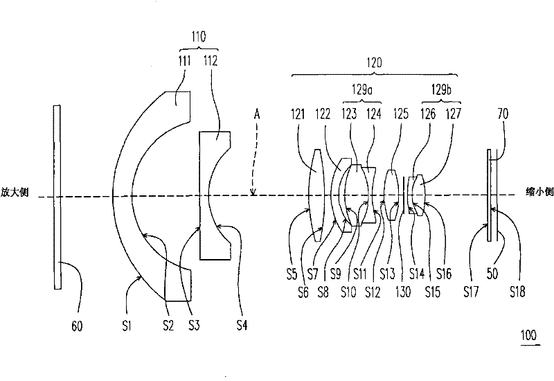
[0048] figure 1 It is a structural schematic diagram of the fixed-focus lens of the first embodiment of the present invention. Please refer to figure 1 , the fixed-focus lens 100 of this embodiment includes a first lens group 110 and a second lens group 120 . The first lens group 110 is disposed between an enlargement side and a reduction side, and includes a first lens 111 and a second lens 112 arranged in sequence from the enlargement side to the reduction side. Both the diopter of the first lens 111 and the second lens 112 are negative, the first lens 111 is an aspherical lens, and the second lens 112 is a spherical lens. In this embodiment, the first lens 111 is, for example, a convex-concave lens with a convex surface facing the magnification side, and the second lens 112 is, for example, a plano-concave lens with a plane facing the magnification side.

[0049] The second lens group 120 is disposed between the first lens group 110 and the reduction side, and includes a...

no. 2 example

[0073] image 3 It is a structural schematic diagram of the fixed-focus lens of the second embodiment of the present invention. Please refer to image 3 , the fixed-focus lens 100' of the present embodiment is the same as the above-mentioned fixed-focus lens 100 (such as figure 1 shown) are similar, and the differences between the two are described below. In this embodiment, the first lens group 110' of the fixed-focus lens 100' may further include a tenth lens 113 disposed between the second lens 112' and the third lens 121. The second lens group 120' may further include an eleventh lens 128 disposed between the third lens 121 and the fourth lens 122. The diopters of the tenth lens 113 and the eleventh lens 128 are, for example, negative and positive, respectively, and both are spherical lenses. In addition, in this embodiment, the relative positions of the third lens 121 and the eleventh lens 128 remain fixed, and the third lens 121 and the eleventh lens 128 are used to ...

no. 3 example

[0087] Figure 4 It is a structural schematic diagram of the fixed-focus lens according to the third embodiment of the present invention. Please refer to Figure 4 , the fixed-focus lens 100 " of the present embodiment is the same as the above-mentioned fixed-focus lens 100 (such as figure 1 shown) are similar, and the differences between the two are described below. In this embodiment, the first lens group 110" of the fixed-focus lens 100" may further include a tenth lens 113', which is disposed between the second lens 112" and the third lens 121. The second lens group 120" An eleventh lens 128 ′ may be further included, which is disposed between the third lens 121 and the fourth lens 122 . The diopters of the tenth lens 113' and the eleventh lens 128' are, for example, negative and positive, respectively, and both are spherical lenses. In addition, in this embodiment, the positions of the first lens group 110″, the fifth lens 123, the sixth lens 124, the seventh lens 125...


PUM


Abstract

The invention relates to a fixed-focus lens which comprises a first lens group and a second lens group. The first lens group is configured between an amplifying side and a shrinking side and comprises a first lens and a second lens which are sequentially arranged from the amplifying side to the shrinking side, wherein the diopters of both the first lens and the second lens are negative, and the first lens is a non-spherical lens. The second lens group is configured between the first lens group and the shrinking side and comprises a third lens, a fourth lens, a fifth lens, a sixth lens, a seventh lens, an eighth lens and a ninth lens which are sequentially arranged from the amplifying side to the shrinking side, wherein the diopters of the third lens to the ninth lens are sequentially positive, negative, positive, negative, positive, negative and positive.

Description

【Technical field】 [0001] The present invention relates to a lens, in particular to a fixed-focus lens. 【Background technique】 [0002] With the development of display technology, a new generation of displays - such as liquid crystal display (LCD), plasma display panel (PDP) and projection apparatus (projection apparatus) - has gradually replaced the traditional cathode ray tube ( cathode ray tube, CRT). Among them, flat panel displays such as liquid crystal displays and plasma displays can occupy a large household market due to their thinner thickness. On the other hand, the projection device can occupy a certain market proportion because it can provide a super-large-sized screen (for example, larger than 52 inches) at a relatively low cost. In addition, the super-sized screen can be watched by many people, which is helpful for the conduct of meetings, the presentation of presentations or the display of teaching materials. This is one of the main reasons why projection dev...

Claims


Application Information

Patent Timeline
Patent Type & Authority Patents(China)
IPC IPC(8): G02B9/04
Inventor 苏元宏曾建雄康尹豪
Owner YOUNG OPTICS
Why Eureka
Try Eureka