
Metal alloy castings with cast-in-place tubes for fluid flow

A technology of casting alloys and casting magnesium alloys, which is applied to engine components, cylinder heads, cylinders, etc., and can solve problems such as corrosion

Inactive Publication Date: 2010-12-01
GM GLOBAL TECH OPERATIONS LLC
View PDF6 Cites 7 Cited by
  • Summary
  • Abstract
  • Description
  • Claims
  • Application Information

AI Technical Summary

Problems solved by technology

But this alloy can be corroded by aqueous coolants and lubricants

Method used


Image

  • Metal alloy castings with cast-in-place tubes for fluid flow
  • Metal alloy castings with cast-in-place tubes for fluid flow
  • Metal alloy castings with cast-in-place tubes for fluid flow

Examples


Embodiment Construction

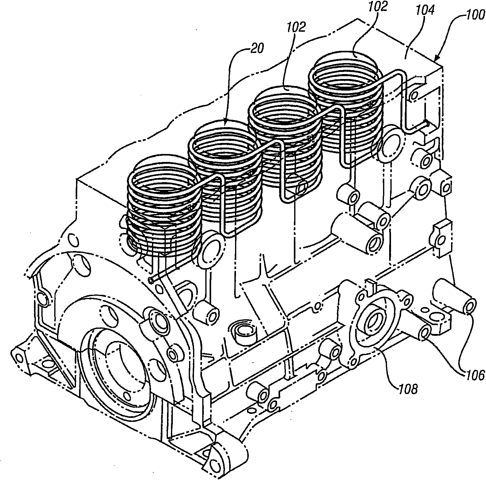
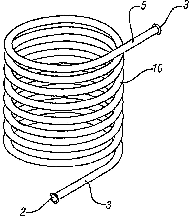
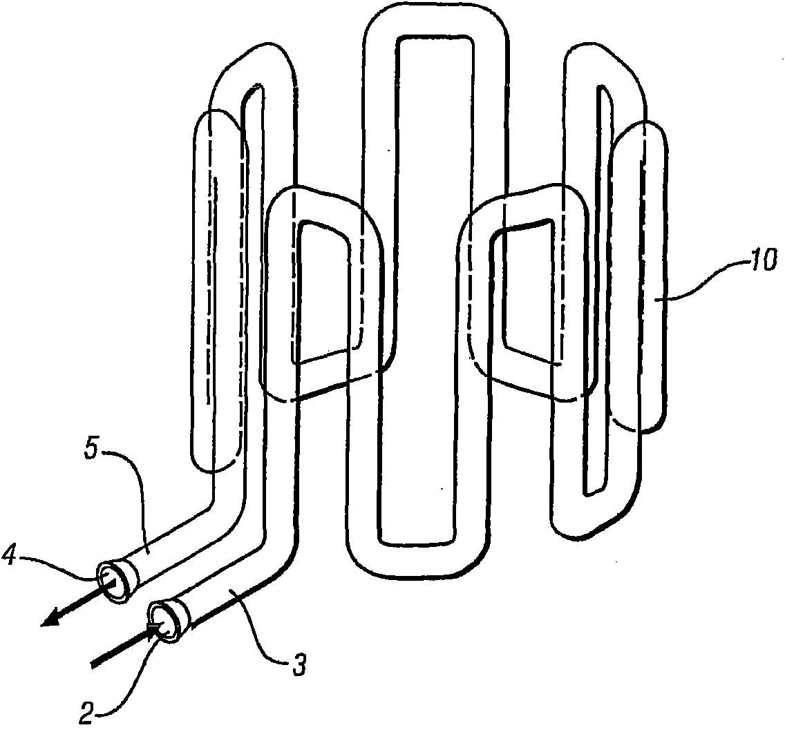
[0046] figure 1 is a diagrammatic view of the invention applied to a representative four-cylinder engine block generally incorporating the features and attributes of such components. A cylinder block or engine block 100 shown in outline is a machined casting comprising cylinders 102 for the pistons of a multi-cylinder reciprocating internal combustion engine. Typically, the deck 104 of the engine is machined as a flat surface capable of mating with a cylinder head (not shown) with a minimum of gaskets. The body is also adapted to allow the cylinder head and crankcase to be attached, while providing attachment points (e.g., perforated boss 106) and mounting flanges (e.g., shown at 108) for auxiliary mechanisms (e.g., AC generators, fuel pumps, etc.), including passages for coolants and lubricants.

[0047] The interconnected tubular structures 20 intended for circulation of engine coolant by means of separate coils surrounding the cylinders 102 are shown fully embedded in the...


PUM


Abstract

The invention relates to a metal alloy casting with cast-in-place tubes for fluid flow. A major engine casting, such as an engine block or a cylinder head, fabricated of either magnesium or aluminum alloy, has a cast-in-place metal tube or form embedded within it. The tube or form enables circulation of liquid while substantially physically isolating the casting alloy from the circulating liquid and thereby restricting or eliminating corrosive interaction between them.

Description

technical field [0001] The present invention relates to metal alloy castings with cast-in-place metal tubes for fluid circulation channels. More specifically, the present invention relates to metal alloy castings with cast-in tubes for coolant flow or other fluid flow, wherein the metal or metal alloy composition of the tubes allows the formation of the casting, insulates the casting from corrosion by the fluid, and can be Castings provide reinforcement. As an example, a magnesium alloy engine block for a reciprocating internal combustion engine may be cast using copper tubes, stainless steel tubes, etc. Magnesium alloys are not corroded by aqueous coolants. Background technique [0002] There is a continuing need to reduce the weight of metal castings employed in many manufactured items. This need is especially evident when castings are used in motor vehicles. Relatively lightweight metal alloys are available for this application. But when cast products come into conta...

Claims


Application Information

Patent Timeline
Patent Type & Authority Applications(China)
IPC IPC(8): B22D15/02
CPCB22D19/0009F05C2201/028F05C2201/903F02F1/24F02F1/00
Inventor G·宋B·R·小鲍威尔E·P·贝克A·K·萨奇德夫T·A·佩里
Owner GM GLOBAL TECH OPERATIONS LLC
Learn More