
Synchronous hydraulic system of diffluence motor

A shunt motor and hydraulic system technology, applied to servo motors, fluid pressure actuators, mechanical equipment, etc., can solve the problem of increased cumulative synchronization errors of four hydraulic cylinders, affecting the life of hydraulic cylinders and shunt motors, and difficulty in continuous production, etc. problem, to achieve the effect of increasing the difficulty of installation, avoiding the phenomenon of suction, and preventing the phenomenon of suction

Active Publication Date: 2012-01-04
CHINA NAT HEAVY MACHINERY RES INSTCO
View PDF0 Cites 2 Cited by
  • Summary
  • Abstract
  • Description
  • Claims
  • Application Information

AI Technical Summary

Problems solved by technology

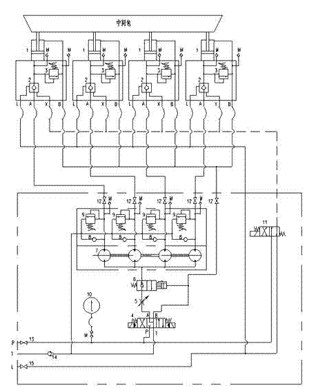
Although the above figure 1 The system shown has considered in detail the functions of the four hydraulic cylinders, such as reversing, synchronization, gravity balance, position locking, safety, oil replenishment, etc., but the following problems still exist in actual use: (1) The four hydraulic cylinders are only in the lowest position. or the highest position to eliminate the synchronous cumulative error; (2) In continuous casting production, the tundish is required to be controlled at a lower position by four hydraulic cylinders for several hours for a long time, and the tundish is adjusted within the range of the lower position at regular intervals Continue to maintain after reaching the new position. This requirement makes the cumulative synchronization error of the four hydraulic cylinders continue to increase and cannot be eliminated for a long time, making it difficult to carry out continuous production for a long time; (3) Due to the existence of synchronization errors, the four hydraulic cylinders If it does not reach the lowest position at the same time, there will be insufficient oil supply due to leakage and other problems, which will cause the hydraulic cylinder that has reached the lowest position to be sucked, which will seriously affect the life of components such as hydraulic cylinders and shunt motors.

Method used


Image

  • Synchronous hydraulic system of diffluence motor
  • Synchronous hydraulic system of diffluence motor
  • Synchronous hydraulic system of diffluence motor

Examples


Embodiment Construction

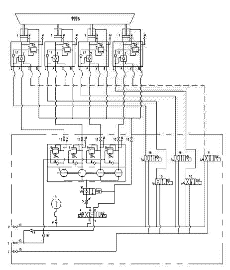
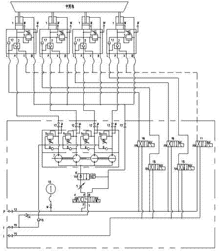
[0014] Such as figure 2 As shown, a shunt motor synchronous hydraulic system includes at least four hydraulic cylinders 1 connected to the tundish, a shunt motor 7, a first one-way valve 8, an overflow valve 9 and a first stop valve 12. The four hydraulic cylinders 1 Drive the tundish up and down, use the splitter motor 7 and the connected first one-way valve 8, overflow valve 9 and first stop valve 12 to synchronously control the positions of the four hydraulic cylinders 1, each hydraulic cylinder 1 is connected to a hydraulic control One-way valve 2 and safety relief valve 3, the hydraulic control one-way valve 2 is controlled by electromagnetic reversing valve 11 for locking the position of the hydraulic cylinder, that is, the position of the tundish, and a fourth one-way valve 17 is installed in the piston chamber of the hydraulic cylinder One end of the fourth one-way valve 17 is connected to the piston chamber of the hydraulic cylinder 1, and the other ends of the four ...


PUM


Abstract

The invention relates to a hydraulic system, in particular to a synchronous hydraulic system of a diffluence motor, which is at an arbitrary position and can compensate synchronous errors, and the synchronous hydraulic system of the diffluence motor is characterized in that: piston cavities of a hydraulic cylinder are respectively provided with a fourth one-way valve one end of which is communicated with the piston cavities of the hydraulic cylinder, and the other ends of the four fourth one-way valves are respectively connected with a two-position four-way electromagnetic reversing valve, oil drainage from a hydraulically controlled one-way valve is connected to an oil way between the fourth one-way valves and the electromagnetic reversing valve, and the two-position four-way electromagnetic reversing valve is connected with the fourth one-way valves, a pressure oil supply way P of a hydraulic pump station and an oil drainage way L of the hydraulic pump station respectively. The invention provides the synchronous hydraulic system of the diffluence motor which can be at the arbitrary position and compensate the synchronous errors, does not produce an inhaling empty phenomenon, avoids accumulation of the synchronous errors, can work continuously for a long term in the arbitrary position in the middle and keep the position, and does not increase the number of oil holding ports out of hydraulic cylinder devices, namely, dose not increasing the installation difficulty.

Description

technical field [0001] The invention relates to a hydraulic system, in particular to a shunt motor synchronous hydraulic system capable of compensating synchronous error at any position. Background technique [0002] In the continuous casting machine production line in the metallurgical field, the tundish is located on the tundish car, and the tundish is driven up and down by four hydraulic cylinders. When the tundish truck is running, the tundish should be lifted to a high position, and after reaching the continuous casting pouring position, the tundish should be lowered to a lower position. At the continuous casting pouring position, the molten steel in the ladle is continuously poured into the tundish from the upper part of the tundish. Open, the molten steel is continuously injected into the crystallizer through the submerged nozzle for continuous casting production. In continuous casting production, the tundish is controlled at a lower position by four hydraulic cylin...

Claims


Application Information

Patent Timeline
Patent Type & Authority Patents(China)
IPC IPC(8): F15B11/22
Inventor 郭星良丘铭军艾春璇解通护
Owner CHINA NAT HEAVY MACHINERY RES INSTCO
Learn More