
Vehicle-mounted lamp with structure for preventing chassis deformation

A deformation structure and chassis technology, which is applied to vehicle components, optical signals, signal devices, etc., can solve problems such as the lamp head and the pan/tilt being stuck, the tip of the gear 60 under force, the teeth of the gear 60, and the gap between the gear 60 and the expansion. performance, enhanced reliability

Inactive Publication Date: 2010-12-01
OCEANS KING LIGHTING SCI&TECH CO LTD +1
View PDF4 Cites 6 Cited by
  • Summary
  • Abstract
  • Description
  • Claims
  • Application Information

AI Technical Summary

Problems solved by technology

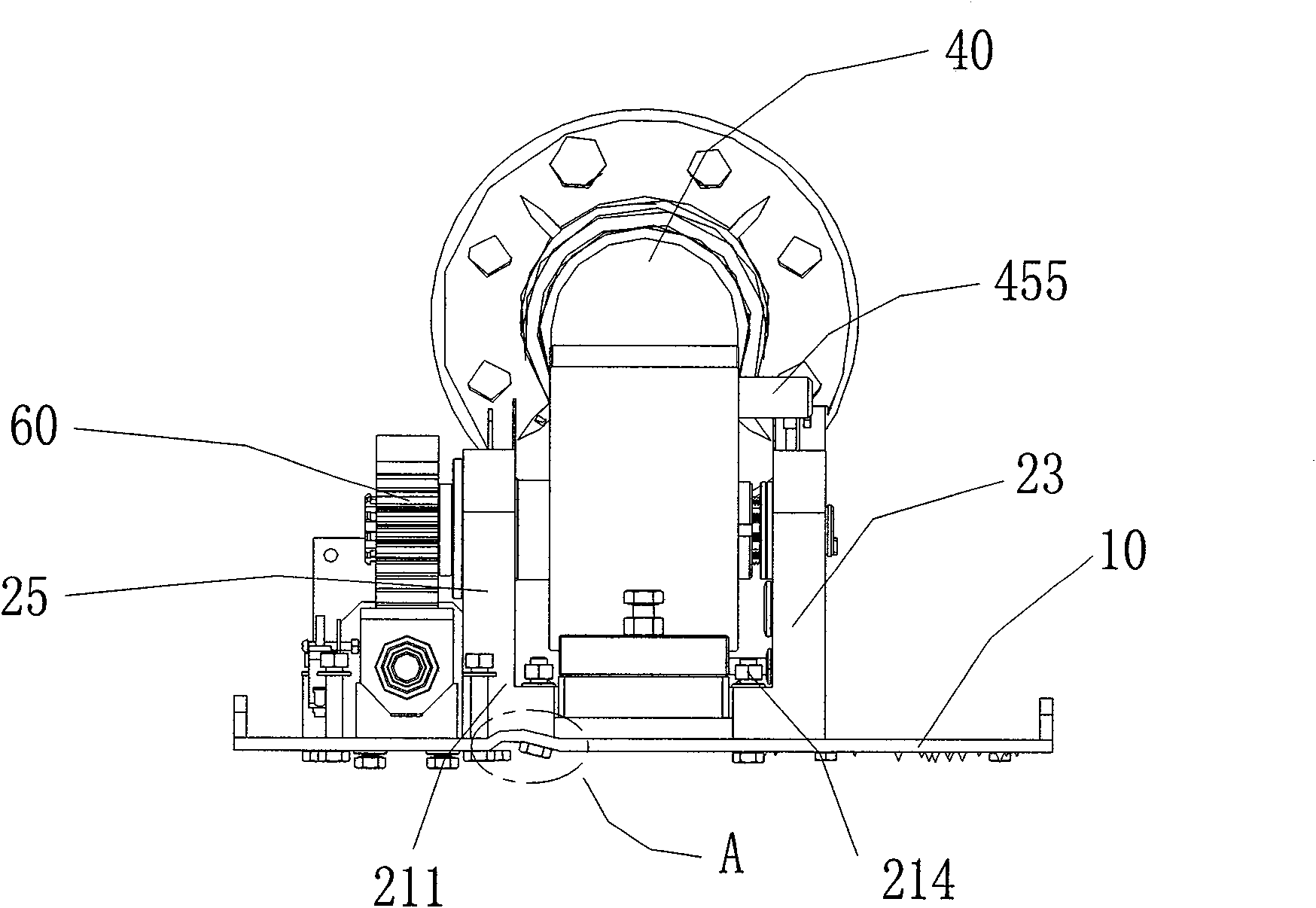
[0004] The chassis 10 without reinforced edges will be seriously deformed, causing the cylinder 40 to deflect, which will cause the gap between the gears 60 to expand and form a vicious circle, and finally cause the lamp head and the head (not shown in the figure) to fall below the designated position and get stuck, while the gears Too much force on the tip of the 60 leads to chipped teeth, and the entire set of vehicle lamps fails
[0005] The deformation phenomenon of the chassis 10 with reinforcing edges (not shown) all around it is improved to a certain extent compared with the chassis without reinforcing edges. It is inconvenient to assemble and disassemble the fixing bolts (211, 214) on 10
And because the chassis 10 is the basis of the whole set of vehicle lamps 30, almost all parts are assembled on the chassis 10, so it is difficult to maintain and replace, and damages often have to be returned to the factory for repair, reducing the reliability and scalability of the vehicle lamps

Method used


Image

  • Vehicle-mounted lamp with structure for preventing chassis deformation
  • Vehicle-mounted lamp with structure for preventing chassis deformation
  • Vehicle-mounted lamp with structure for preventing chassis deformation

Examples


Embodiment Construction

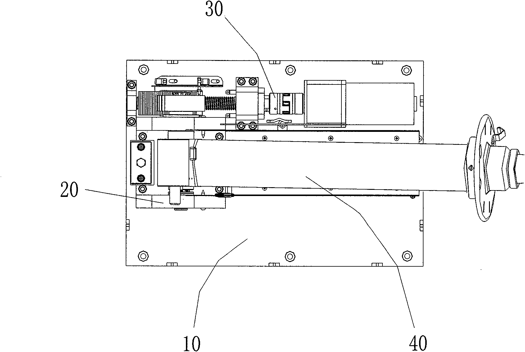
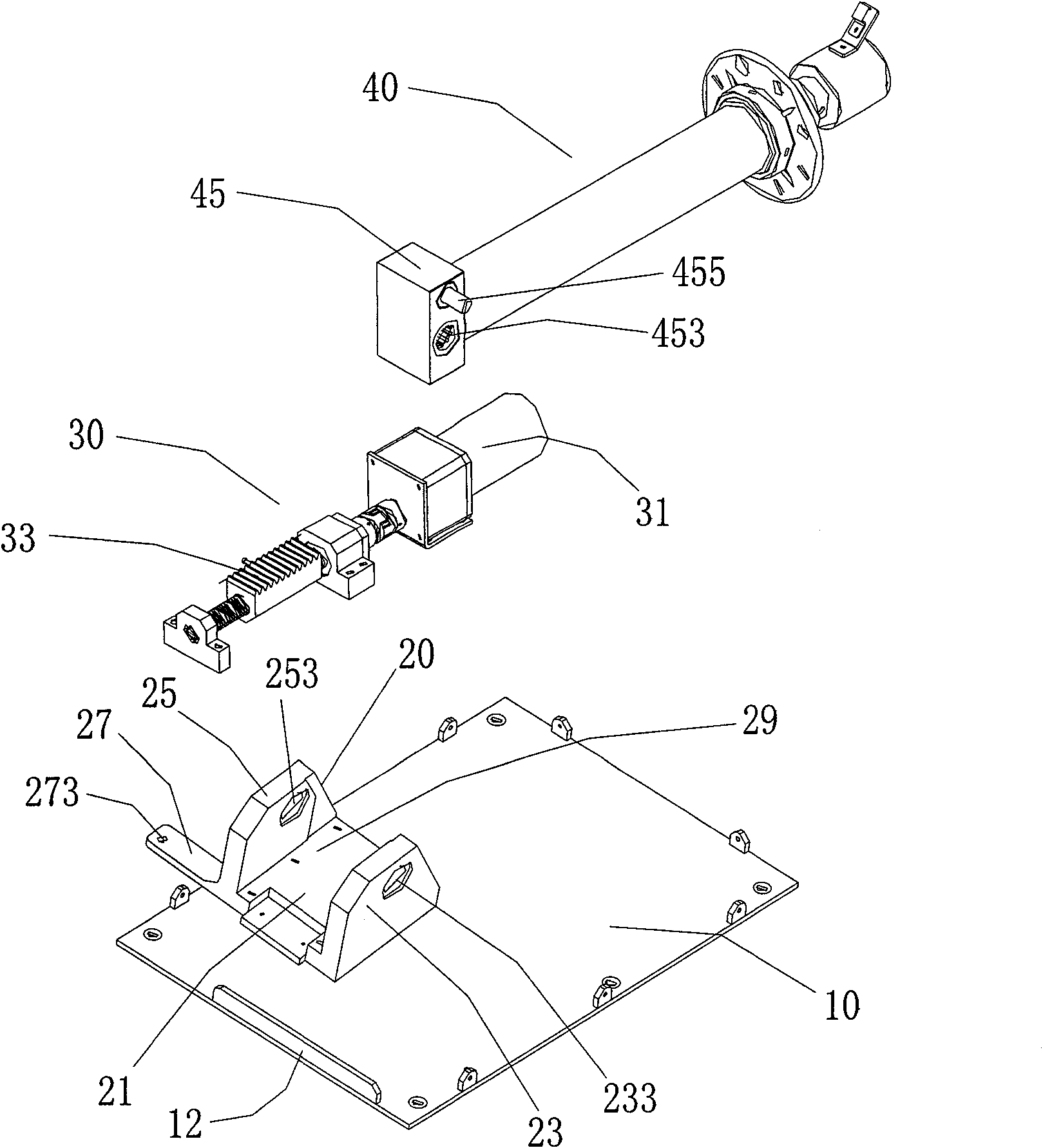
[0018] Please combine image 3 and Figure 4 As shown, they are respectively an exploded view and a top view of the parts on the vehicle-mounted lamp with a chassis deformation-preventing structure according to the present invention. The vehicle-mounted lamp 3 with a chassis-deformation-preventing structure includes: a square chassis 10, a mast fixing seat 20, and an upright propulsion mechanism 30 , lifting cylinder 40; mast holder 20 and vertical propulsion mechanism 30 are adjacently fixed on the chassis 10, mast holder 20 includes a base 21 and a corresponding first support arm 25 protruding from the base 21 With the second support arm 23, the base 21 and the two support arms (25, 23) form a concave-shaped accommodation groove 29, and one end of the lift cylinder 40 is connected to the vehicle-mounted lamp platform 41 and the lamp holder 42, and the other end is The connecting portion 45 is hinged to the support arms ( 25 , 23 ) and placed in the receiving groove 29 of th...


PUM


Abstract

The invention relates to a vehicle-mounted lamp with structure for preventing chassis deformation, comprising a chassis, a mast fixing seat, an up-down pushing mechanism and a lift cylinder, wherein the mast fixing seat and the up-down pushing mechanism are fixed on the chassis; the mast fixing seat comprises a substrate, a first support arm and a second support arm convexly arranged on the substrate correspondingly; the substrate and the two support arms form a concave accommodating groove; one end of the lift cylinder is connected with the vehicle-mounted lamp and a holder and the other endis a connection part with a connection hole; the connection part is in rotation connection with the accommodating groove of the mast fixing seat; at least one support lug at the same plane as the substrate is arranged in the surrounding of the substrate of the mast fixing seat; the side on the chassis near the mast fixing seat is provided convexly with a reinforcing edge; under the coaction of the reinforcing edge and the support lug of the mast fixing seat, the chassis is not easy to deform, and the lift cylinder after many times of use will not incline and deflect as a result of chassis deformation, thereby greatly enhancing reliability of the vehicle-mounted lamp.

Description

technical field [0001] The invention relates to an anti-deformation structure, in particular to an anti-deformation structure applied to the chassis of a vehicle lamp. Background technique [0002] Vehicle-mounted liftable lamps can be installed on cars or fixed objects, can be automatically lifted and reset, are easy to operate and use, and have omni-directional positioning functions. They have been widely used in satellite news interview vehicles, broadcast vehicles, military vehicles, and public security command vehicles. , emergency communication vehicles and other special vehicles and other types of vehicles. [0003] Such as figure 1 and figure 2 As shown, they are the rear view and top view of the vehicle-mounted lamps without reinforcing edges in the chassis of the prior art after long-term use. The chassis 10 of the prior art vehicle-mounted lamps are all made of steel plates without reinforcing edges or all surrounding reinforcements are provided. Edge structur...

Claims


Application Information

Patent Timeline
Patent Type & Authority Applications(China)
IPC IPC(8): B60Q1/02
Inventor 周明杰何奇猛
Owner OCEANS KING LIGHTING SCI&TECH CO LTD
Learn More