Steel coil tensioning device of full-automatic uncoiler

A tensioning device and uncoiler technology, which is applied in the field of steel coil tensioning devices, can solve problems such as troublesome oblique expansion blocks, shortened service life, and large wear, and achieves increased application range, good tensioning effect, and low manufacturing cost Effect

Active Publication Date: 2010-12-01
ZHEJIANG JINGGONG SCI & TECH
View PDF0 Cites 32 Cited by
  • Summary
  • Abstract
  • Description
  • Claims
  • Application Information

AI Technical Summary

Problems solved by technology

This uncoiler adopts a cantilever structure. In order to ensure that it can bear heavy steel coils, the main shaft used for load-bearing must be thick. In addition, it is very troublesome to process oblique expansion blocks and inner wedges, and they slide on inclined surfaces. To achieve the expansion and contraction of the three claws, the wear is large, and specific surface treatment is required on the friction surface, which leads to the high price and bulky size of this large and heavy-duty uncoiler. It can be seen that for the case of light steel coils, using this The uncoiler of this tensioning method is extremely uneconomical, which is not conducive to popularization and application
This internal tensioning method also requires frequent addition of lubricating oil for maintenance, otherwise it is easy to wear off the working slope of the oblique expansion block and the inner wedge, resulting in shortened service life

Method used


Image

  • Steel coil tensioning device of full-automatic uncoiler
  • Steel coil tensioning device of full-automatic uncoiler
  • Steel coil tensioning device of full-automatic uncoiler

Examples


Embodiment Construction

[0031] The following are specific embodiments of the present invention and in conjunction with the accompanying drawings, the technical solutions of the present invention are further described, but the present invention is not limited to these embodiments.

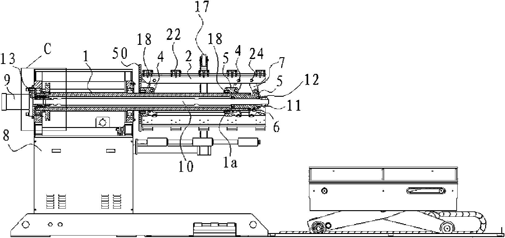
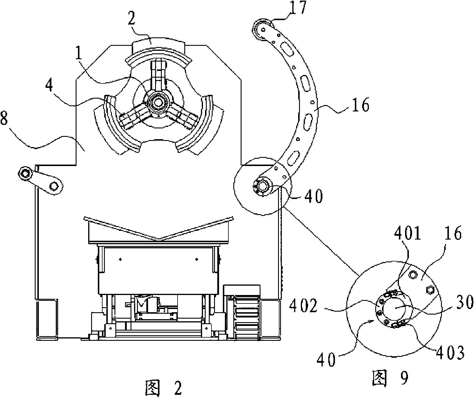
[0032] Such as figure 1 and figure 2As mentioned above, the steel coil tensioning device of the automatic uncoiler is arranged on the base 8 of the automatic uncoiler, including a hollow rotating shaft 1 and three tensioning plates 2 evenly distributed on the periphery of the rotating shaft 1, such as As shown in the figure, the tensioning plate 2 includes an arc-shaped inner brace 21 and five arc-shaped outer braces 22, the outer braces 22 are evenly distributed on the outer side of the inner brace 21 and screwed 3 fixed, in order to prevent the tension plate 2 from damaging the inner surface of the steel coil, and increase the friction and tension effect at the same time, the outer surfaces of the inner support plate 2...


PUM


Abstract

The invention provides a steel coil tensioning device of a full-automatic uncoiler, belongs to the technical field of uncoilers and overcomes the defects of high price, huge volume, difficult popularization and application and short service life of a conventional large heavy-duty uncoiler. The steel coil tensioning device of the full-automatic uncoiler comprises a hollow rotary shaft of which one end part serves as a construction section and the other end serves as a cantilever section, and a plurality of tensioning plates distributed at the periphery of the cantilever section of the rotary shaft; the construction section of the rotary shaft is connected to a base; a connection rod is arranged between each tensioning plate and the rotary shaft; one end of the connection rod is hinged to the corresponding tension plate, while the other end is hinged to the rotary shaft; and the tensioning plate is connected with a spreading / shrinking mechanism capable of driving all tensioning plates to spread or shrink at the same time. The tensioning device has the advantages of low manufacturing cost, adaptability to various steel coils with different specifications and relatively light weight, less abrasion, good tensioning effect and long maintenance period.

Description

technical field [0001] The invention belongs to the technical field of fully automatic uncoilers, and relates to a steel coil tensioning device, in particular to a steel coil tensioning device applied to a fully automatic uncoiler. Background technique [0002] In the plate processing industry, large-scale rolling equipment is usually used to continuously press and form metal plates. In order to facilitate production, improve efficiency and reduce labor intensity, the raw material plates used are pre-wound into cylindrical steel coils and stored in special on the charging rack so that it is kept in a reasonably controlled state. An uncoiler is a device that unrolls a cylindrical steel coil continuously or intermittently. [0003] At present, there are many forms of uncoilers. From the function, there are mainly mechanical passive uncoilers, semi-automatic uncoilers, automatic uncoilers and other uncoilers. No matter what kind of uncoiler, there is a steel coil on it. Devic...

Claims


Application Information

Patent Timeline
Patent Type & Authority Applications(China)
IPC IPC(8): B65H16/02B65H75/24B21C47/18B21C47/28
Inventor 盛小锋裘建义徐淼炎夏荣祥
Owner ZHEJIANG JINGGONG SCI & TECH
Why Eureka
Try Eureka