Film-coating device

A technology of a coating device and a coating chamber, which is applied in sputtering coating, ion implantation coating, vacuum evaporation coating and other directions, can solve the problem of uneven thickness of the film layer, and achieve the effect of uniform consumption and improvement of uniformity.

Inactive Publication Date: 2013-03-20
HONG FU JIN PRECISION IND (SHENZHEN) CO LTD +1
View PDF2 Cites 0 Cited by
  • Summary
  • Abstract
  • Description
  • Claims
  • Application Information

AI Technical Summary

Problems solved by technology

When the shape of the substrate to be plated is relatively complex, the cross-sectional area of ​​some surfaces to be plated on the substrate to be plated relative to the target plane is relatively small, so the film layers plated on these surfaces to be plated are larger than those on other surfaces. Thin, resulting in uneven thickness of the coating layer on the substrate to be coated

Method used


Image

  • Film-coating device
  • Film-coating device
  • Film-coating device

Examples


Embodiment Construction

[0009] The present invention will be further described in detail below in conjunction with the accompanying drawings.

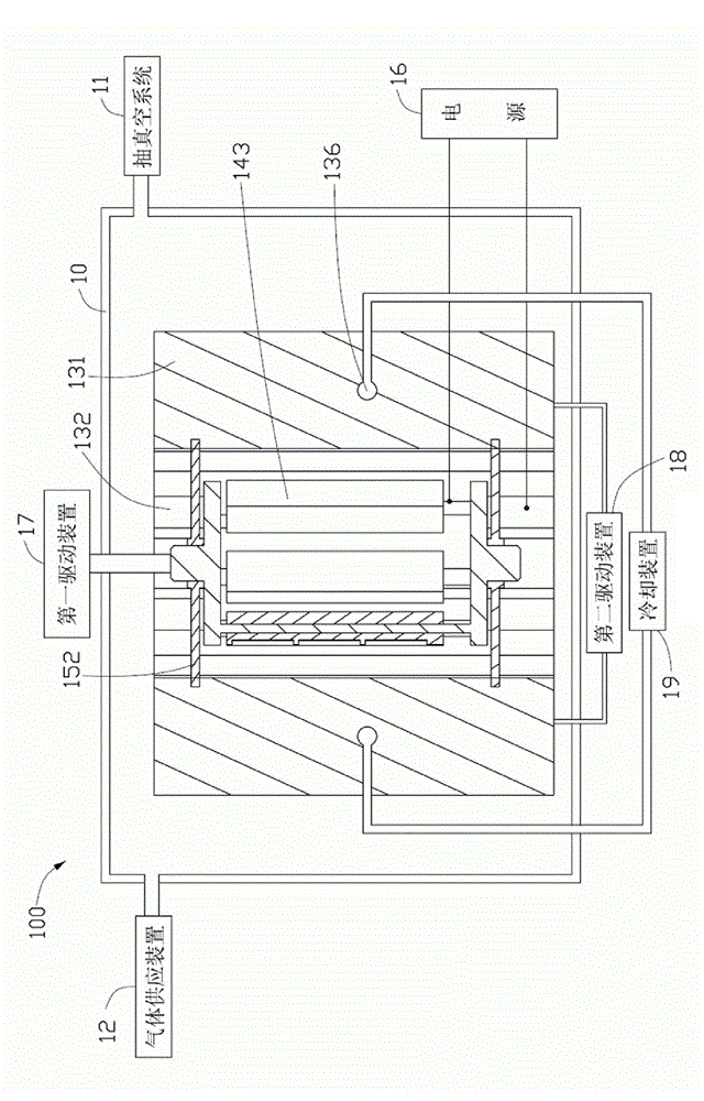
[0010] figure 1 Shown is a coating device 100 provided by an embodiment of the present invention, which includes a coating chamber 10, a vacuum system 11, a gas supply device 12, a target carrier device 13, a substrate carrier device 14, two Connecting device 15 , a power source 16 , a first driving device 17 , a second driving device 18 and a cooling device 19 .

[0011] The coating chamber 10 is used for accommodating the target carrying device 13 , the substrate carrying device 14 and the connecting device 15 .

[0012] The vacuum system 11 communicates with the coating chamber 10 and is used for extracting the gas in the coating chamber 10 .

[0013] The gas supply device 12 communicates with the coating chamber 10 and is used for supplying reaction gas, such as argon, to the coating chamber 10 .

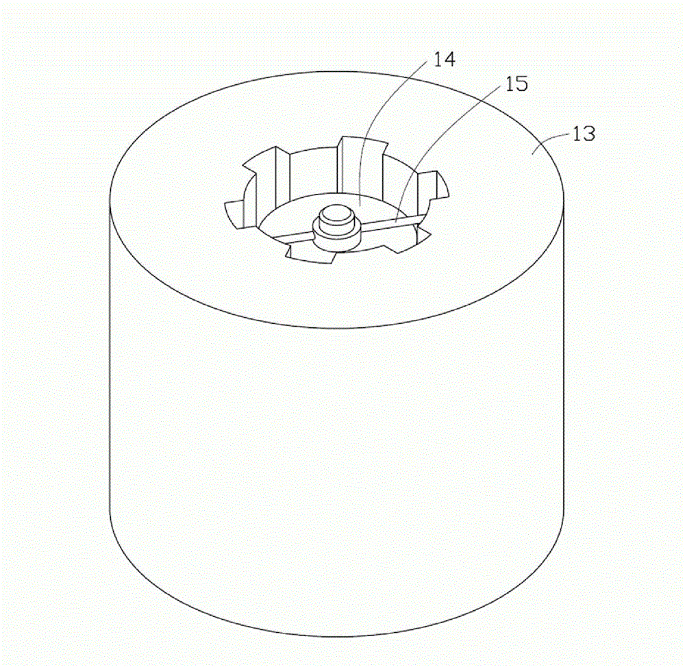
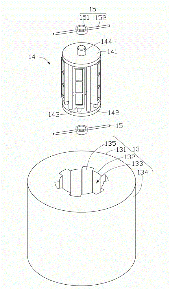
[0014] see figure 2 and image 3 , the target carry...


PUM


Abstract

A magnetron sputtering device includes a target holder, a substrate holder, and a first driver. The target holder defines a sputtering space therein, and includes at least one target tray arranged at a periphery of the sputtering space. The substrate holder is rotatably positioned in the sputtering space. The first driver is connected to the substrate holder. The first driver is operable to rotate the substrate holder relative to the target holder.

Description

technical field [0001] The invention relates to a coating device. Background technique [0002] The sputtering device usually sets the substrate to be plated opposite to the target, and uses plasma to bombard the target, so that the atoms of the target are sputtered onto the substrate under the action of the plasma to form a film layer. The current sputtering device generally fixes the target, and the substrate to be plated can translate relative to the target, but cannot rotate relative to the target. When the shape of the substrate to be plated is relatively complex, the cross-sectional area of ​​some surfaces to be plated on the substrate to be plated relative to the target plane is relatively small, so the film layers plated on these surfaces to be plated are larger than those on other surfaces. Thin, resulting in uneven thickness of the coating layer on the substrate to be coated. Contents of the invention [0003] In view of this, it is necessary to provide a coati...

Claims


Application Information

Patent Timeline
Patent Type & Authority Patents(China)
IPC IPC(8): C23C14/34C23C14/56
CPCH01J37/3423H01J37/3405C23C14/35H01J37/3435
Inventor 裴绍凯
Owner HONG FU JIN PRECISION IND (SHENZHEN) CO LTD
Why Eureka
Try Eureka