
Dispersed cable saddle structure for bridge

A technology for cable saddles and bridges, applied in bridges, bridge parts, bridge construction and other directions, can solve the problems of large concrete stress, difficult to guarantee, large rotation and sliding resistance, etc., to achieve reasonable stress diffusion, convenient maintenance, and flexible rotation. Effect

Active Publication Date: 2011-09-07
CHENGDU XINZHU ROAD & BRIDGE MASCH CO LTD +2
View PDF0 Cites 4 Cited by
  • Summary
  • Abstract
  • Description
  • Claims
  • Application Information

AI Technical Summary

Problems solved by technology

The structure of the loose cable saddle is mainly realized by the arc-shaped steel contact surface. Its rotation angle is small, it is difficult to rotate and slide, and there is a lack of rotation flexibility and sliding adjustment. The rotation and sliding resistance is large, and it is difficult to ensure that the loose cable Uniform stress distribution on scatter cables
The above-mentioned line contact surface is easy to damage the contact arc, which leads to the failure of the loose cable saddle function. At the same time, it adopts line contact, which transmits a large stress to the concrete, and the lower plate needs to be thicker to ensure the concrete stress.
In addition, limited by the shape and structure of the saddle body, the height of the saddle body is large under the premise of the force distribution requirements, so the height of the entire saddle is relatively high, and the stability of the high center of gravity is poor.

Method used


Image

  • Dispersed cable saddle structure for bridge
  • Dispersed cable saddle structure for bridge
  • Dispersed cable saddle structure for bridge

Examples


Embodiment Construction

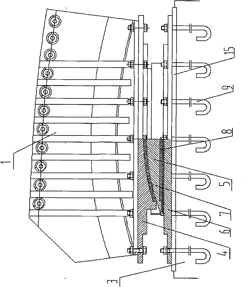
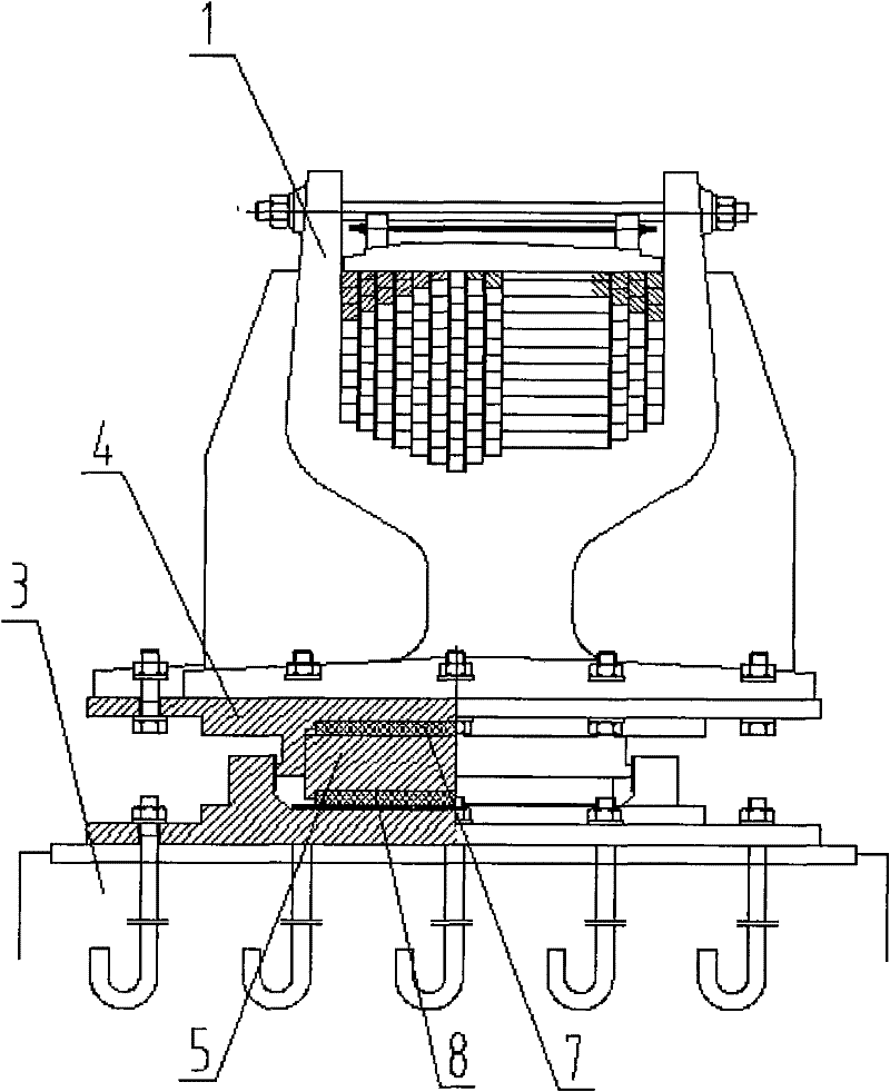
[0017] like figure 1 , 2 Shown: a loose cable saddle structure for bridges, a saddle head 1, a saddle assembly and a pad stone 3, the saddle head 1 is supported on the pad stone 3 through the saddle assembly, it is characterized in that : the saddle assembly includes an upper support plate 4, an intermediate liner 5 and a lower support plate 6, a cylindrical fit is formed between the upper support plate 4 and the intermediate liner 5 and a column is arranged between the two surface slide plate 7, a plane slide plate 8 is arranged between the middle lining plate 5 and the lower bearing plate 6, the saddle head 1 is fixed on the upper bearing plate 4, and the lower bearing plate 6 is fixed on the On the stepping stone 3.

[0018] A lower anchor bolt 9 is embedded in the pad stone 3 , and a steel plate 15 is connected to the upper end of the anchor bolt 9 , and the lower support plate 6 is fixed on the steel plate 15 .

[0019] The cylindrical slide 7 and the flat slide 8 are...


PUM


Abstract

The invention discloses a dispersed cable saddle structure for a bridge, comprising a saddle bow (1), a saddle component and a pad stone (3); the saddle bow (1) is supported on the pad stone (3) through the saddle component; the saddle component comprises an upper support base plate (4), a middle lining plate (5) and a lower support base plate (6); a cylindrical surface sliding plate (7) is arranged between the upper support base plate (4) and the middle lining plate (5) in cylindrical fit; a plane sliding plate (8) is arranged between the middle lining plate (5) and the lower support base plate (6); the saddle bow (1) is fixed on the upper support base plate (4); and the lower support base plate (6) is fixed on the pad stone (3). The invention overcomes the defects of the traditional saddle through the design of the saddle bow supporting structure, thereby having the characteristics of safety and reliability, flexible rotation, rational stress spread, convenient regulation and convenient maintenance.

Description

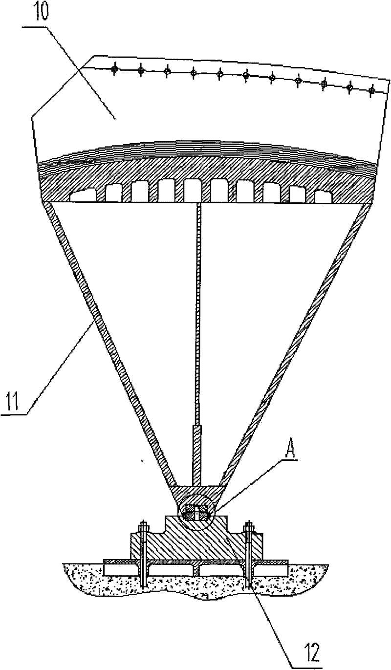
technical field [0001] The invention belongs to the technical field of bridges, and in particular relates to a loose cable saddle structure for bridges. Background technique [0002] At present, traditional scatter saddles such as image 3 , 4 , shown in 5: mainly include saddle head 10, cross-section is the saddle body 11 of inverted triangle, base 12, saddle head 10 is welded on the upper end of saddle body 11, between saddle body 11 and base 12 through the upper connection block of elongated shape 13 and the lower connecting block 14 are connected, and a rotating pin is also arranged between the upper connecting block 13 and the lower connecting block 14, and a linear contact surface is formed between the saddle body 11 and the upper connecting block 13, and the structure adopts a mixed structure of casting-welding , the pommel part is made of cast steel, and the saddle is welded by steel plate. The structure of the loose cable saddle is mainly realized by the arc-shape...

Claims


Application Information

Patent Timeline
Patent Type & Authority Patents(China)
IPC IPC(8): E01D19/14
Inventor 夏玉龙熊劲松周亮刘海亮陈太华
Owner CHENGDU XINZHU ROAD & BRIDGE MASCH CO LTD
Learn More