Cast-in-place concrete hollow slab

A hollow slab and cast-in-place concrete technology, which is applied in the field of cast-in-place concrete hollow slabs, can solve problems such as inconvenient production, inability to arrange hollow carcass, and influence on floor construction quality

Inactive Publication Date: 2010-12-01
湖南邱则有专利战略策划有限公司
View PDF3 Cites 1 Cited by
  • Summary
  • Abstract
  • Description
  • Claims
  • Application Information

AI Technical Summary

Problems solved by technology

But when this kind of hollow carcass is applied to the floor construction, the hollow carcass cannot be accurately arranged in the middle layer of the floor, which affects the construction quality of the floor
For this reason, the patent number is ZL01215092.4, and the utility model patent titled "Building Components" discloses a building component that is a polyhedron, which can be hollow or solid. It is arranged in the middle layer of the floor, and the outer wall of the polyhedron is provided with protruding legs, so that when the floor is poured, the legs can ensure that the hollow multi-faceted main cavity is just at the middle layer of the floor. , so as to better solve the above problems, but this kind of cast-in-place concrete hollow slab is inconvenient to make during production, the production efficiency is low, and the corresponding cost is high

Method used


Image

  • Cast-in-place concrete hollow slab
  • Cast-in-place concrete hollow slab
  • Cast-in-place concrete hollow slab

Examples


Embodiment Construction

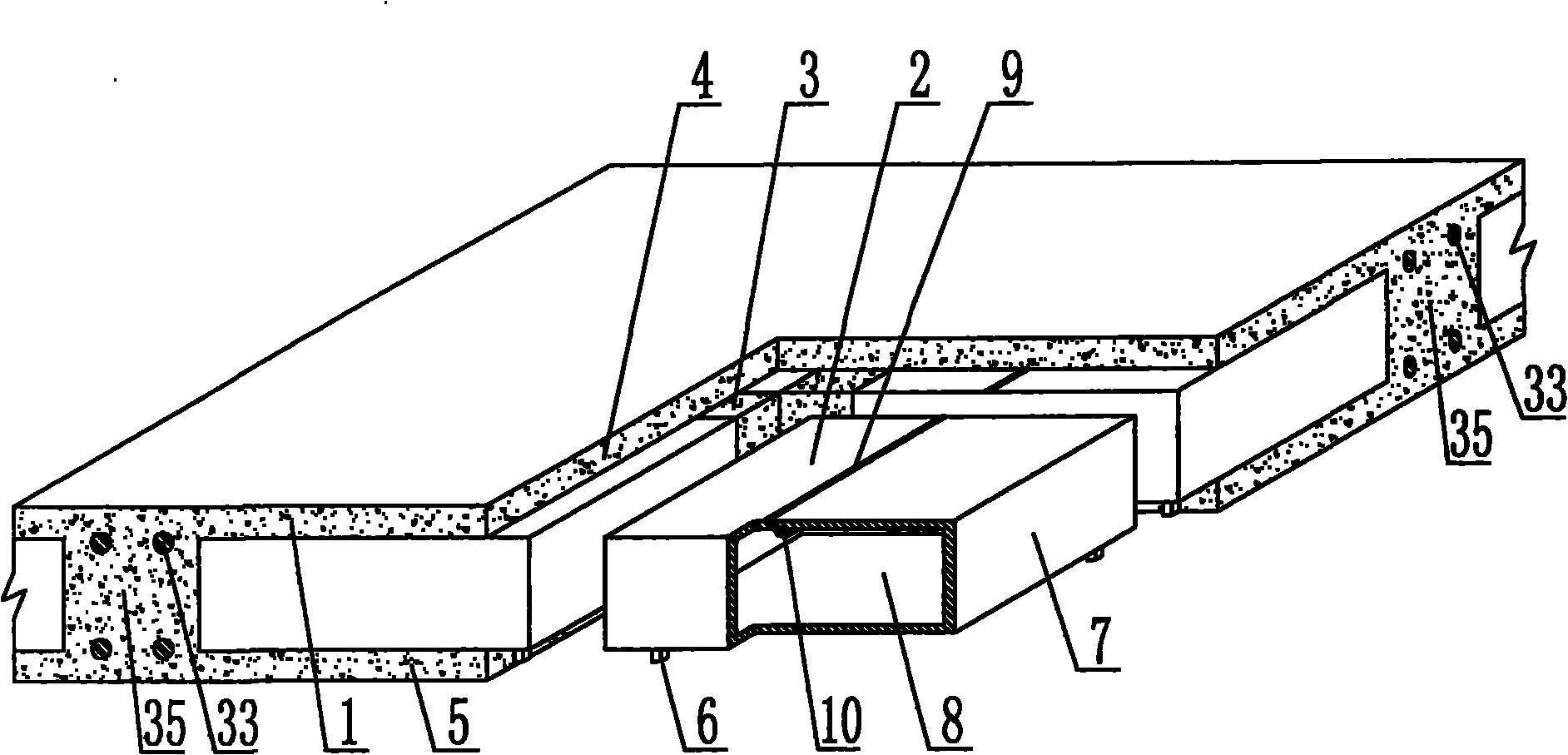
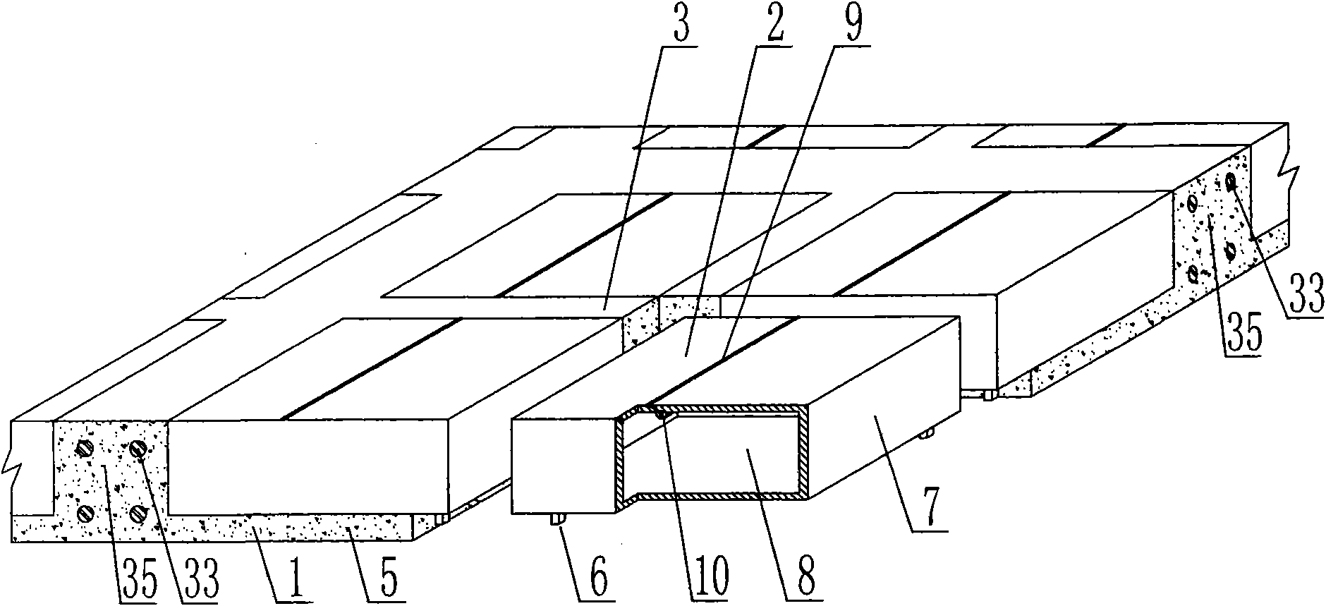
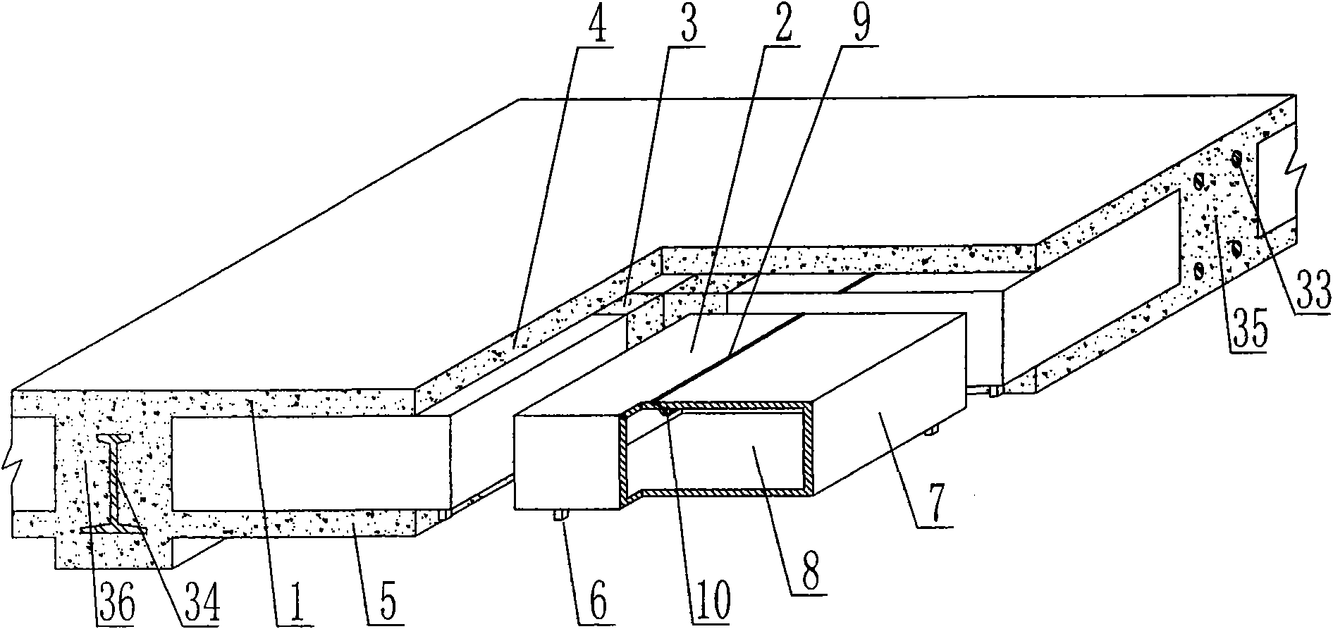
[0082] The present invention will be further described below in conjunction with the accompanying drawings and embodiments.

[0083] As shown in the accompanying drawings, the present invention comprises a reinforced concrete 1 and a hollow carcass 2, the hollow carcass 2 is wrapped in the reinforced concrete 1, the hollow carcass 2 are arranged alternately, and there are cast-in-situ reinforced concrete ribs 3 between them. It is an upper plate 4 of cast-in-place reinforced concrete, under which is a lower plate 5 of cast-in-place reinforced concrete, and the hollow carcass 2 is provided with supporting feet 6, and the supporting feet 6 are arranged on the outer wall 7 of the hollow carcass 2, and the outer wall 7 is enclosed to form The hollow carcass 2 with a cavity 8 is characterized in that the embryo body of the outer wall 7 of the hollow carcass 2 is a conjoined integral embryo body, and the embryo body is enclosed and then joined and cemented to form a hollow tire Body...


PUM


Abstract

The invention discloses a cast-in-place concrete hollow slab. The cast-in-place concrete hollow slab comprises reinforced concrete (1) and hollow matrixes (2), wherein the hollow matrixes (2) are wrapped in the reinforced concrete (1) and arranged at intervals; cast-in-place reinforced concrete ribs (3) are arranged between every two hollow matrixes; an upper cast-in-place reinforced concrete plate (4) is arranged on the cast-in-place reinforced concrete ribs, and a lower cast-in-place reinforced concrete plate (5) is arranged below the cast-in-place reinforced concrete ribs; the hollow matrixes (2) are provided with supporting legs (6) which are arranged on the outer walls (7) of the hollow matrixes (2); the outer walls (7) are enclosed to form the hollow matrixes (2) with cavities (8); the cast-in-place concrete hollow slab is characterized in that blanks on the outer walls (7) of the hollow matrixes (2) are connected integral blanks; the blanks are joined after being enclosed and the edges of the blanks are glued to form the hollow matrixes (2); gluing tapes (9) are formed on the gluing parts; the inner side of at least one joint gluing tape (9) is provided with a carrying die (10); the blank joint gluing tapes (9) are arranged at the corners of the hollow matrixes (2); and the carrying die (10) is integrally overlapped with the gluing tape (9) by gluing. The hollow matrix has the advantages of simple manufacturing, high production efficiency, high integrality, low cost and one-step molding.

Description

[0001] This application is a divisional application of an invention patent application with an application date of February 15, 2006, an application number of 2006100091576, and a title of “a cast-in-place concrete hollow slab”. (1) Technical field [0002] The invention relates to a cast-in-place concrete hollow slab. (2) Background technology [0003] At present, the cast-in-place concrete hollow floor is a widely used floor structure. The lightweight permanent tire molds filled in it include various hollow tubes and boxes, and the boxes are hollow or solid. For example, the patent No. ZL99249798.1, which the applicant applied for on November 29, 1999, is a utility model patent named "fiber-reinforced thin-walled member for reinforced concrete filling", which discloses a thin-walled formwork member, including an upper plate, The surrounding side walls, the lower bottom, and the upper plate, the surrounding side walls and the lower bottom form a polyhedral cavity. Another ...

Claims


Application Information

Patent Timeline
IPC IPC(8): E04B5/18E04B5/36E04G15/06
Inventor 邱则有
Owner 湖南邱则有专利战略策划有限公司
Why Eureka
Try Eureka