Hose pump

A hose pump and hose technology, applied in the field of peristaltic pumps, can solve the problems of small pump housing see-through lens, abnormal noise, hose damage, etc., to ensure pumping efficiency and stability, increase service life, and reduce wear and tear. Effect

Inactive Publication Date: 2010-12-01
吴俊
View PDF7 Cites 10 Cited by
  • Summary
  • Abstract
  • Description
  • Claims
  • Application Information

AI Technical Summary

Problems solved by technology

This kind of hose pump has certain deficiencies: First, when the hose pump is working, the side guide rollers located on both sides of the hose are continuously squeezed by the hose. Under the action of bending moment, the side guide roller is easy to bend outward at the junction with the rotor, causing the side guide roller sleeve and the guide roller shaft to lock up, and the non-rotation forms sliding friction, which causes hard damage to the hose; secondly , in actual use, the connection between the side guide roller shaft and the rotor is threaded. During the use of the hose pump, one side of the guide roller must be loose, and the loose side guide roller will withstand the pump casing, causing the pump to be damaged. The copper sleeve between the guide roller sleeve and the guide roller shaft in the side guide roller is unevenly stressed under the action of high-frequency hose pulsation, and will wear out after a period of time. After wear, the entire side guide roller sleeve and guide roller The shaft gap increases, making abnormal noise, and the overall wear and tear will be accelerated if the work continues. The cost is extremely high. If it is not replaced, the hose will be damaged soon; The bearing positioned by the main shaft makes it inconvenient to disassemble and maintain the hose pump, and the perspective lens on the pump casing is too small, so it is often difficult to observe the working conditions in the pump

Method used


Image

  • Hose pump
  • Hose pump
  • Hose pump

Examples


Embodiment Construction

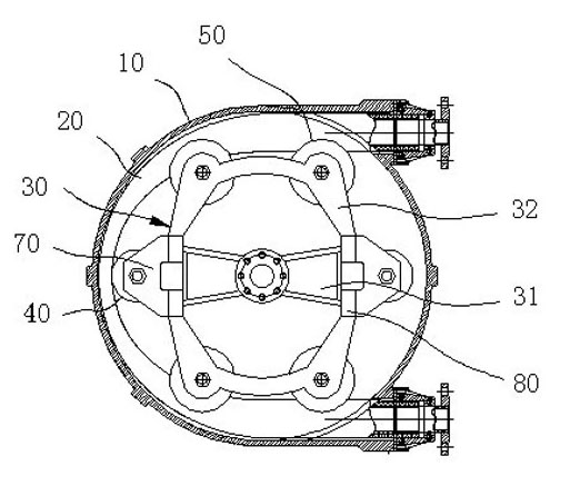
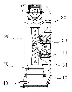
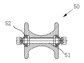
[0011] A hose pump such as figure 1 , including a pump casing 10, an end cover 90 provided on one side of the pump casing 10, and a hose 20 arranged along the circumferential inner wall of the pump casing 10. Both ends of the hose 20 extend to the outside of the pump casing 10 and are fixed. There is a rotor 30 and a main shaft 60 concentric with the rotor 30 for driving the rotor 30 , and the outer periphery of the rotor 30 is provided with a pressure roller 40 , which together with the circumferential inner wall of the pump casing 10 constitutes intermittent extrusion of the hose 20 Cooperate, the outer periphery of rotor 30 is also provided with sheave 50, and sheave 50 is supported and fixed by rotating shaft 51, as image 3 The two ends of the rotating shaft 51 are fixed on the rotor 30. The rotating shaft 51 and the rotor 30 are parallel to the center of rotation of the pressing roller 40. The arc of the bottom coincides with the arc surface of the outer wall of the hos...


PUM


Abstract

The invention belongs to the field of peristaltic pumps, and particularly relates to a hose pump. The hose pump comprises a pump shell, an end cover arranged on one side of the pump shell and a hose arranged along the peripheral inner wall of the pump shell; two ends of the hose extend to the exterior of the pump shell and are fixed; a rotor and a main shaft concentric with the rotor for driving the rotor are arranged in the pump shell; the periphery of the rotor is provided with a pressing roll; the pressing roll and the peripheral inner wall of the pump shell form intermittent extrusion fit for the hose; the periphery of the rotor is also provided with a groove wheel which is supported and fixed by a rotating shaft; two ends of the rotating shaft are fixedly arranged on the rotor; the rotating shaft and the rotor are parallel to the gyration center of the pressing roll; and the cross section of an upper groove of the groove wheel is U-shaped, the bottom arc line of the U-shaped groove of the groove wheel is matched with the cambered surface of the outer wall of the hose, and the width of a notch of the groove wheel is matched with the outside diameter of the hose. The hose pump has the advantages of high pumping efficiency, low energy consumption and long service life.

Description

technical field [0001] The invention belongs to the field of peristaltic pumps, in particular to a hose pump. Background technique [0002] There are many kinds of industrial pumps used for fluid transportation in modern industrial production. The hose pumps used to transport slurry fluids with high viscosity, strong corrosion and high solid content belong to the category of industrial pumps. Patent No. 94223444.8 discloses a hose pump. The hose pump consists of a pump casing, an end cover on one side of the pump casing, a hose arranged along the inner wall of the pump casing, and a rotor located in the pump casing and concentric with the pump casing. , composed of pressure rollers and side guide rollers installed on the outer periphery of the rotor. The pressure roller is fixed on the iron frames on both sides of the rotor, and the side guide roller is suspended at one end and fixed on the rotor at the other end. The side guide roller is composed of a guide roller shaft a...

Claims


Application Information

Patent Timeline
Patent Type & Authority Applications(China)
IPC IPC(8): F04B43/08
Inventor 吴俊
Owner 吴俊
Why Eureka
Try Eureka