Water level pumping and lowering device for hydraulic engineering construction

A technology for water conservancy engineering and water level, applied in infrastructure engineering, construction, etc., can solve problems such as reducing equipment reliability, reducing energy efficiency, and not being able to reduce it, so as to reduce the dependence on sensing equipment, reduce the total amount of water pumped, and reduce The effect of equipment cost

Active Publication Date: 2022-04-19
LIAOCHENG YELLOW RIVER ENG BUREAU
View PDF0 Cites 0 Cited by
  • Summary
  • Abstract
  • Description
  • Claims
  • Application Information

AI Technical Summary

Problems solved by technology

[0003] When maintaining the groundwater level, the amount of pumped water and the amount of incoming water are generally in a state of balance. However, the permeability and water permeability of the formations in different locations and at different times are different. Select the water pump with the corresponding flow rate respectively. Therefore, at any time period, it is impossible to guarantee that the water pumping volume and incoming water volume of each well are exactly the same, that is, some wells will be drained quickly, and the water level of some wells will not drop. On the one hand, Reduces pumping efficiency, on the other hand, idling reduces energy efficiency and there is waste
[0004] Secondly, the equipment usually controls the valve and water pump through the upper and lower water level sensing instruments to maintain the water level in an area to ensure that the water level is kept below the standard and the water pump does not need to be started and stopped frequently, but the water level needs to be kept higher than the pit bottom elevation. A large height difference means that more water needs to be pumped and the cost is higher. Secondly, the water pump needs to be started and stopped frequently, which is more likely to be damaged. In addition, the underground environment is also easy to damage the sensor and reduce the reliability of the equipment.

Method used


Image

  • Water level pumping and lowering device for hydraulic engineering construction
  • Water level pumping and lowering device for hydraulic engineering construction
  • Water level pumping and lowering device for hydraulic engineering construction

Examples


Embodiment Construction

[0021] The following will clearly and completely describe the technical solutions in the embodiments of the present invention with reference to the accompanying drawings in the embodiments of the present invention. Obviously, the described embodiments are only some, not all, embodiments of the present invention. Based on the embodiments of the present invention, all other embodiments obtained by persons of ordinary skill in the art without making creative efforts belong to the protection scope of the present invention.

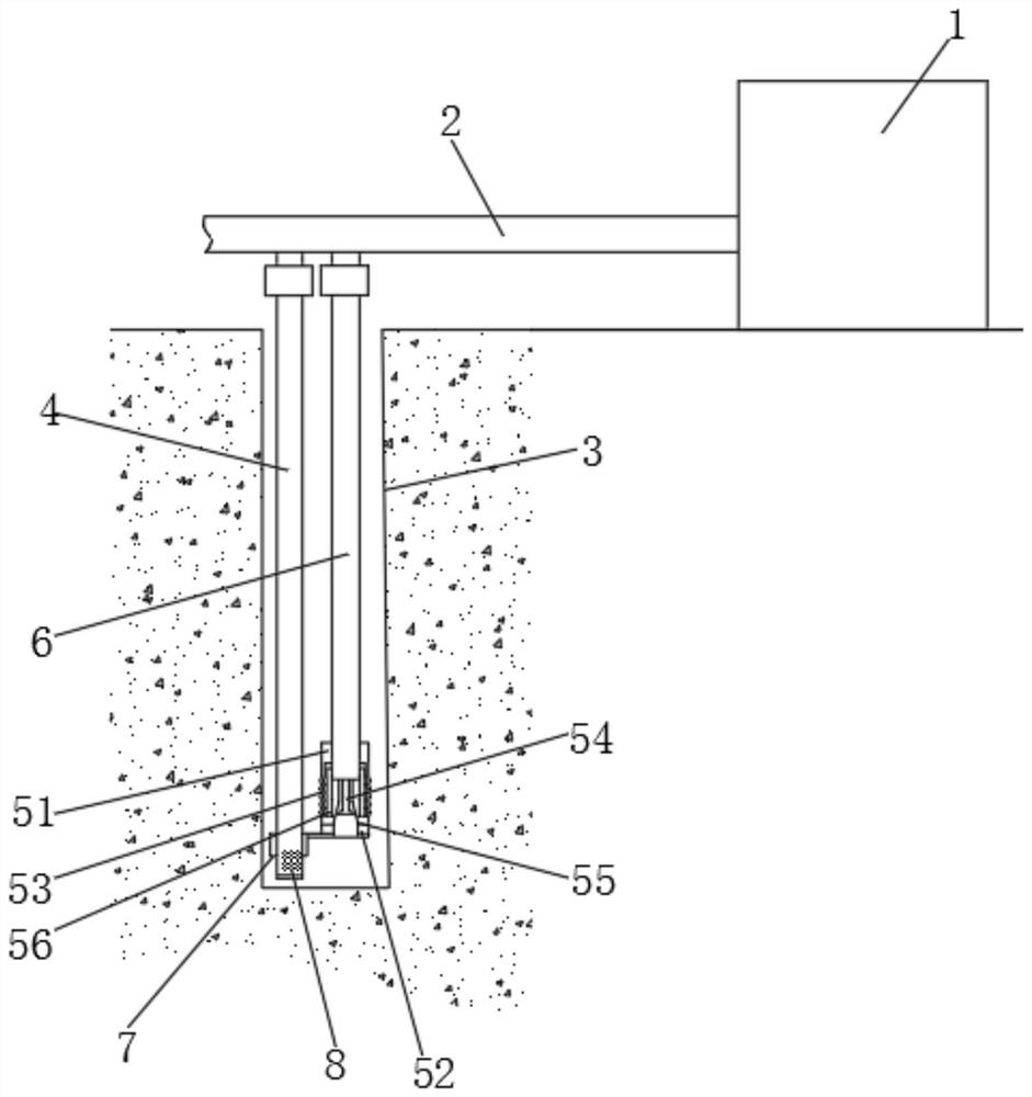
[0022] see figure 1 , a water level pumping and lowering device for water conservancy engineering construction, comprising a pump house 1, a main pipe 2, a filter pipe 3 and a first suction pipe 4, the pump house 1 communicates with the main pipe 2 and uses negative pressure to drive the water flow in the main pipe 2, and the main pipe 2 It communicates with the first suction pipe 4, the first suction pipe 4 is set in the filter tube 3, the outer wall of the f...


PUM


Abstract

The invention relates to the technical field of water conservancy engineering construction equipment, and discloses a water level pumping and lowering device for water conservancy engineering construction, including a pump room, a main pipe, a filter pipe and a first water suction pipe. The pump room is connected with the main pipe and driven by negative pressure Water flows in the main pipe. In this water level pumping device for water conservancy construction, the water absorption speed in each well is self-adapted according to its return water speed, while ensuring that the water in each well drops rapidly, it will not suck up, and the suction of the pump will be reasonably distributed. , maximize the use of water pump suction, improve energy efficiency, and reduce the power requirements of the water pump. Secondly, precipitation and water level maintenance show different water absorption speeds to ensure pumping efficiency. Through the balance of water absorption speed and recovery speed, the water level is maintained. The water pump is always Maintaining a constant working efficiency fundamentally avoids the frequent start and stop of the equipment, and keeping the water level constant also greatly reduces the total amount of pumped water and reduces equipment costs.

Description

technical field [0001] The invention relates to the technical field of water conservancy project construction equipment, in particular to a water level pumping and lowering device for water conservancy project construction. Background technique [0002] Water conservancy projects are mostly constructed in areas such as rivers, coasts, and tidal flats. These areas are mostly fluid soil layers such as upper sand and lower rocks or mud flats. When carrying out deep foundation pit construction in such areas, the well point dewatering method is usually used to lower the groundwater level, that is, a certain number of filter wells are buried around the foundation pit, and water is pumped from them by pumping equipment, so that the groundwater level is always maintained at the level of the bottom of the pit. , until the backfill is completed or the underground structure has sufficient anti-floating capacity. [0003] When maintaining the groundwater level, the amount of pumped wat...

Claims


Application Information

Patent Timeline
Patent Type & Authority Patents(China)
IPC IPC(8): E02D19/06E02D19/10
CPCE02D19/06E02D19/10
Inventor 沈培张伟王晓军张婷婷
Owner LIAOCHENG YELLOW RIVER ENG BUREAU
Why Eureka
Try Eureka