Rail clamping device structure

A technology of rail clamps and splints, which is applied in the field of rail-type X-ray safety inspection systems, and can solve problems such as heavy workload, narrow working space for equipment operators, volume and weight restrictions, etc.

Inactive Publication Date: 2010-12-01
NUCTECH CO LTD
View PDF0 Cites 7 Cited by
  • Summary
  • Abstract
  • Description
  • Claims
  • Application Information

AI Technical Summary

Problems solved by technology

If the security inspection machine is used to work in a fixed workplace, all items need to be transported to the entrance of the security inspection machine one by one for security inspection. This method needs to carry all the inspected goods, and the workload is too large
With the above-mentioned vehicle-mounted mobile inspection equipment, it is necessary to transfer the vehicle-mounted safety inspection system to each inspection place, and the vehicle-mounted mobile inspection equipment has strict restrictions on the volume and weight of the inspected goods, and the working space of the equipment operator is narrow.

Method used


Image

  • Rail clamping device structure
  • Rail clamping device structure
  • Rail clamping device structure

Examples


Embodiment Construction

[0025] The technical solutions of the present invention will be further specifically described below through the embodiments and in conjunction with the accompanying drawings. In the specification, the same or similar reference numerals designate the same or similar components. The following description of the embodiments of the present invention with reference to the accompanying drawings is intended to explain the general inventive concept of the present invention, but should not be construed as a limitation of the present invention.

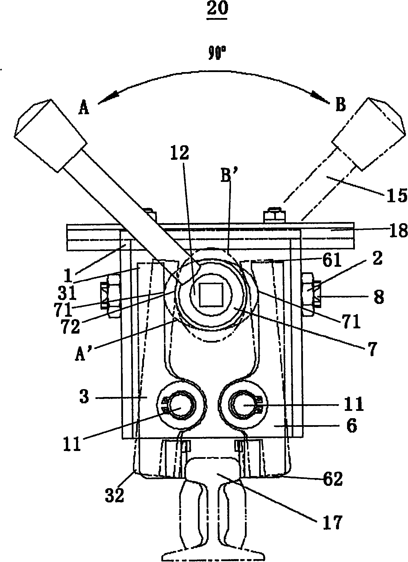
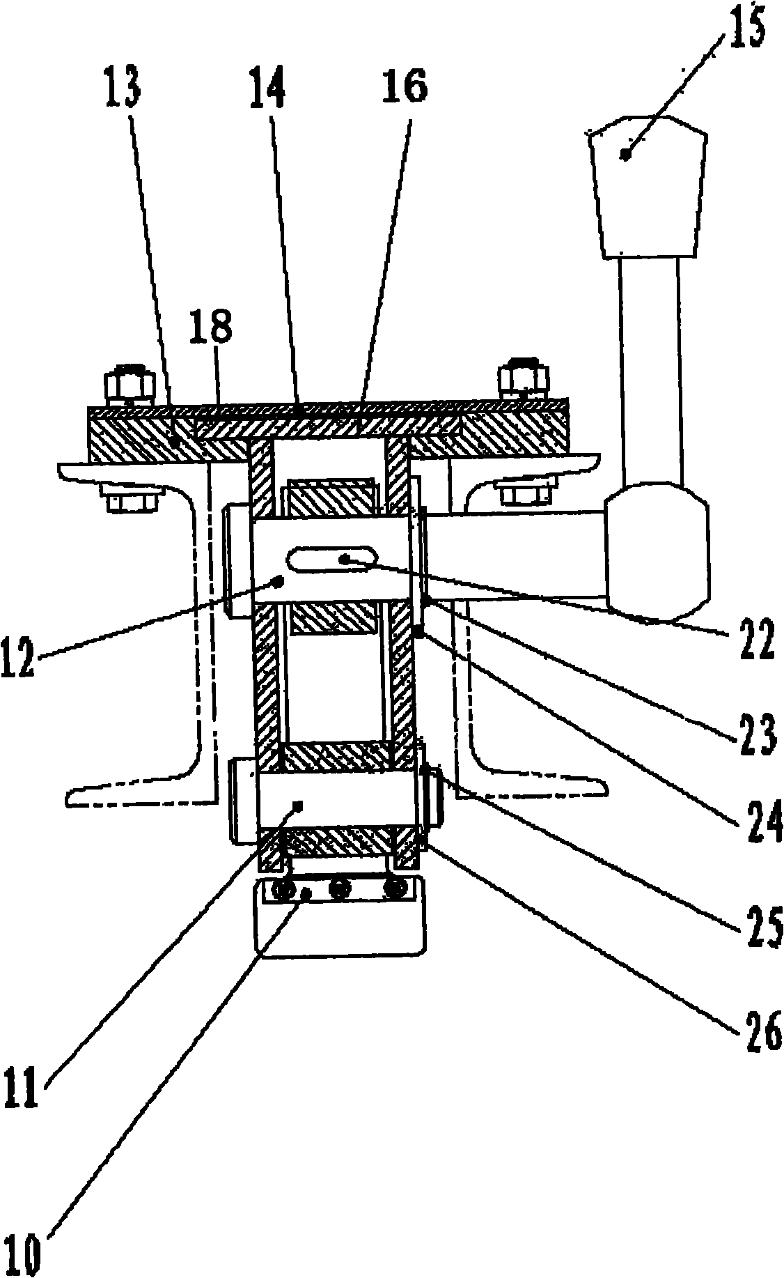
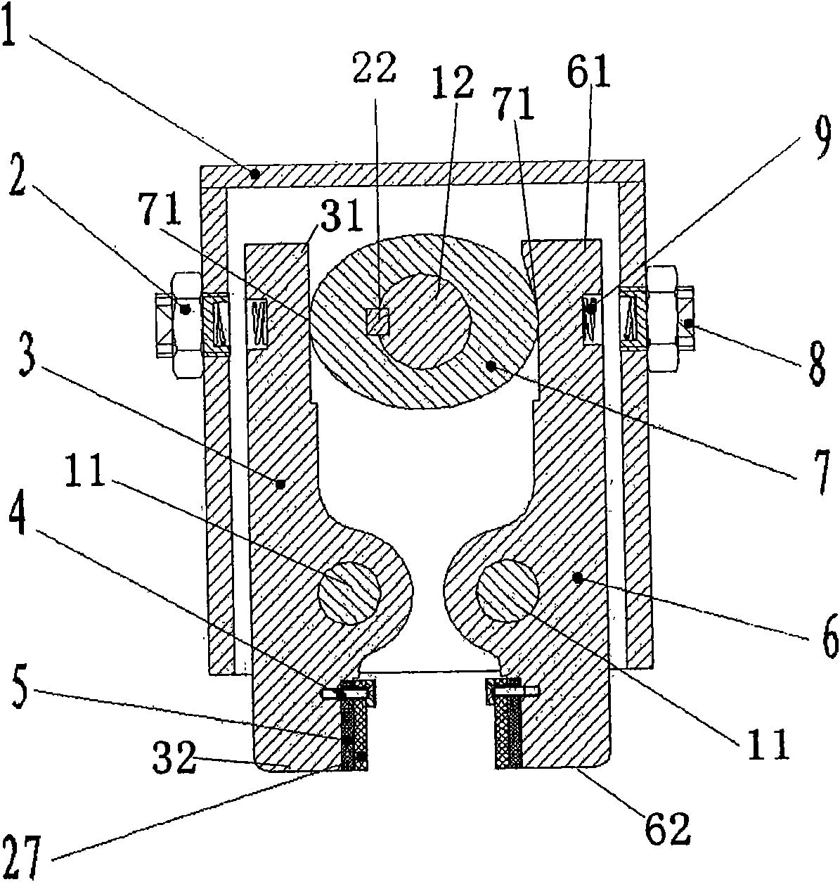
[0026] Such as figure 1 with figure 2 As shown, the present invention provides a rail clamp structure 20, which includes a frame 1, a cam mechanism 7 and at least one clamping plate, such as the two clamping plates 3 and 6 in the figure. The cam mechanism 7 is mounted on the frame 1 and can rotate around its center of rotation. At least one clamping plate 3, 6 is pivotally connected to the frame 1 through a pin shaft 11, wherein one end of...


PUM


Abstract

The invention discloses a rail clamping device structure (20) which comprises a frame (1), a cam mechanism (7) and clamp plates (3, 6), wherein the cam mechanism (7) is installed on the frame (1) and can rotate around the rotating center thereof; the clamp plates (3, 6) are pivoted to the frame (1) through an axis pin (11); one ends of the clamp plates (3, 6) can be connected between a first position (A') and a second position (B') of the cam mechanism (7), thereby driving the clamp plates (3, 6) to pivot around the axis pin (11) and driving the pivoting movement corresponding to the pivoting movement of the clamp plates (3, 6) around the axis pin (11); and the other ends of the clamp plates (3, 6) can respectively form a joint with a rail (17) to realize clamping and disengagement, thereby realizing releasing.

Description

technical field [0001] The invention relates to a rail-type X-ray safety inspection system, in particular to a rail clamp structure used in the system. Background technique [0002] At present, there are two main working modes of the security inspection system: the first one is that during the security inspection operation, the radiation source and detector are not fixed, and the inspection items are scanned through the movement of the radiation source and detector. The second is that the radiation source and the detector are stationary during the security inspection operation, and the inspected items can pass through the radiation scanning area to complete the scanning. Among them, the second working method is divided into two categories: one is a fixed workplace, such as a luggage security inspection system, and the other is an unfixed workplace, such as a vehicle-mounted security inspection system. [0003] In the customs cargo security inspection in some port cities, th...

Claims


Application Information

Patent Timeline
Patent Type & Authority Applications(China)
IPC IPC(8): G01N23/04G01V8/10
Inventor 易裕民何会绍王涟王学武
Owner NUCTECH CO LTD
Why Eureka
Try Eureka