Electronic device and method for operating screen

一种电子装置、控制方法的技术,应用在电数字数据处理、数据处理的输入/输出过程、仪器等方向,能够解决点错、触控式屏幕大小有限等问题

Inactive Publication Date: 2010-12-01
COMPAL ELECTRONICS INC
View PDF3 Cites 7 Cited by
  • Summary
  • Abstract
  • Description
  • Claims
  • Application Information

AI Technical Summary

Problems solved by technology

[0003] For some electronic devices with a relatively light appearance, the size of the touch screen is limited, and users often make mistakes when operating.

Method used


Image

  • Electronic device and method for operating screen
  • Electronic device and method for operating screen
  • Electronic device and method for operating screen

Examples


no. 1 example

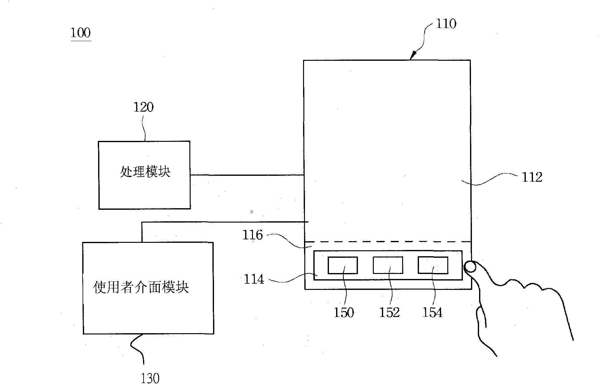
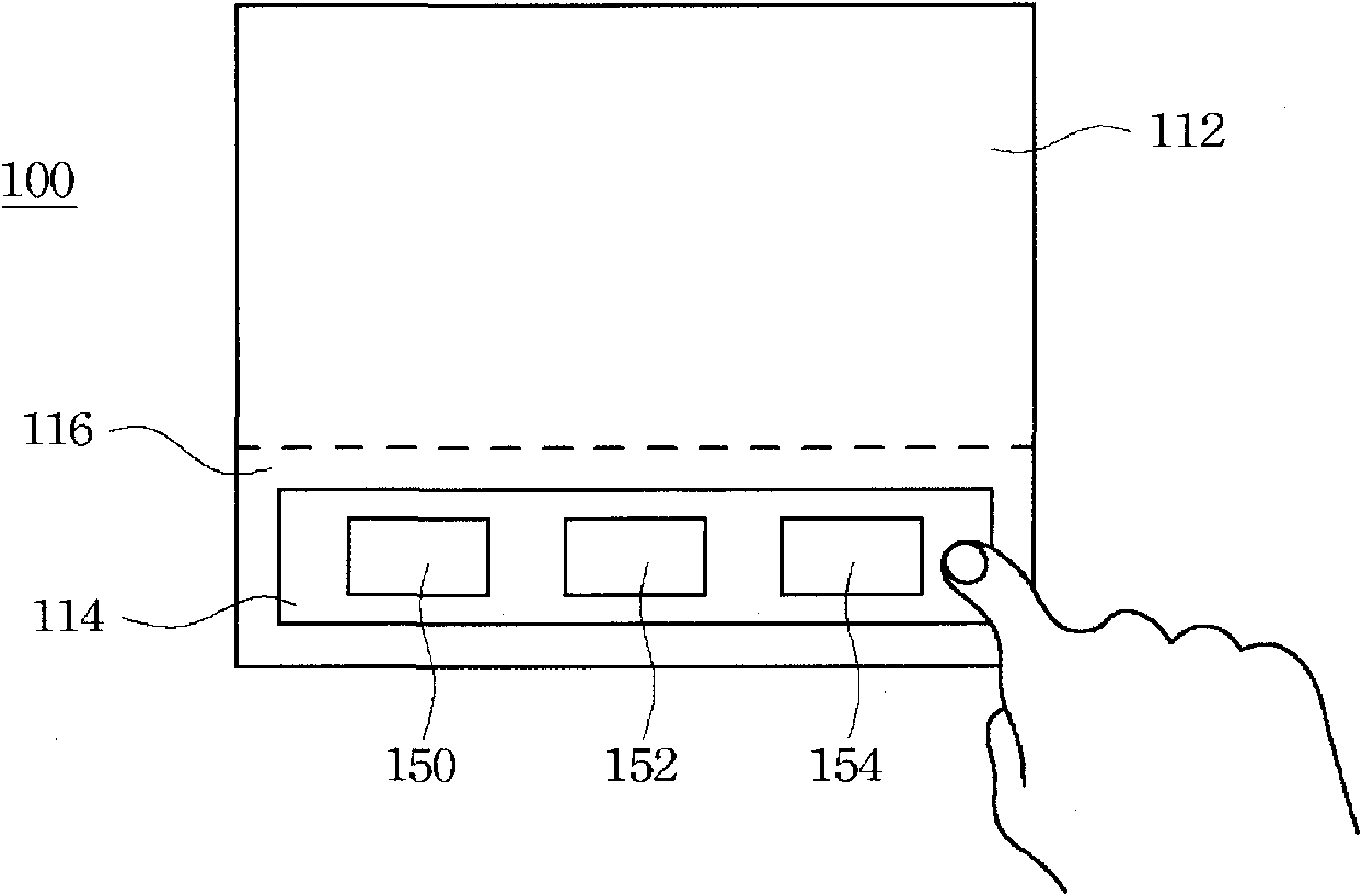
[0043] Please refer to Figure 3a , the screen 110 presets a trigger position A1 , A2 , A3 corresponding to the items 150 , 152 , 154 in the work window 112 . When the pointer drags the selected item 150 to the trigger position A1, the user interface module 130 generates a third sensing signal.

[0044] Such as Figure 3b As shown, the pointer is continuously located in the command window 114, selects the item 150, and drags the selected item 150 to the trigger position A1. Then, the processing module 120 receives the first, second and third sensing signals successively, and opens the item 150 corresponding to the user interface (not shown in the figure) in the work window 112 adjacent to the pointer position.

[0045]In addition, since in this embodiment, the screen 110 has preset trigger positions A1, A2, A3, therefore, after the processing module 120 successively receives the first, second and third sensing signals, it is turned on near the trigger position A1. The user ...

no. 2 example

[0047] In this embodiment, when it is determined that the pointer is located in the command window 114 and the selected item 150, the user interface module 130 generates the first and second sensing signals. The difference from the previous embodiment is that, if Figure 4a As shown, when the pointer drags the item 150 to the work window 112 and stops touching the item 150 in the work window 112, the user interface module 130 generates a third sensing signal, so the processing module 120 continues to The first, second and third sensing signals are received, and the user interface 170 corresponding to the item 150 is opened.

[0048] because Figure 4a Among them, the screen 110 is a touch screen, and the pointer is controlled by the user's finger. When the pointer (finger) drags the item 150 on the work window 112 and leaves the screen 110, it means that the pointer stops dragging and the user interface module 130 generates The third sensing signal. Of course, the action of...

no. 3 example

[0051] In this embodiment, the manner in which the user interface module 130 generates the first and second sensing signals is the same as that in the first and second embodiments, and will not be repeated here. Please refer to Figure 5 As shown, different from the previous embodiments, when the pointer drags the item 150 to the work window 112 and changes the dragging direction, the user interface module 130 generates a third sensing signal. Similarly, the processing module 120 receives the first, second and third sensing signals successively, and opens a user interface (not shown) corresponding to the item 150 .

[0052] In practice, when the pointer is dragged from a first dragging direction D1 to a second dragging direction D2, and when the angle between the first and second dragging directions D1 and D2 is larger than 90 degrees, the user interface module 130 to generate the third sensing signal. If the included angle between the first and second dragging directions D1...


PUM


Abstract

The invention relates to an electronic device and a method for operating screen. The electronic device, comprises: a screen being capable of displaying a working window and an executing window, a user interface module, wherein when a pointer is positioned on the executing window, the user interface module generates a first sensing signal for displaying at least one item on the screen, when the pointer selects the item, the user interface module generates a second sensing signal, and when the pointer drags the item to the working window, the user interface module generates a third sensing signal; and a processing module for continuously receiving the first, second and third sensing signals that are sequentially generated by the user interface module to open a user interface corresponding to the item in the working window, wherein the user interface is adjacent to the pointer. The electronic device and the method for operating screen accords with the operation mode of the human engineering and increases the use convenience.

Description

technical field [0001] The invention relates to an electronic device and a control method of a user interface. Background technique [0002] In recent years, due to the development of industry and commerce and the progress of society, the relatively provided products are mainly aimed at convenience, reliability, and economic benefits. Therefore, the products currently developed are more advanced than before, and can contribute to society. [0003] For some light-weight electronic devices, the size of the touch screen is limited, and users often make mistakes when operating them. Therefore, how to realize an ergonomic operation mode on the screen is one of the current important research and development topics, and has also become a goal that needs to be improved in related fields. Contents of the invention [0004] Therefore, an aspect of the present disclosure is to provide a control method of an electronic device and a user interface. [0005] According to an embodiment...

Claims


Application Information

Patent Timeline
Patent Type & Authority Applications(China)
IPC IPC(8): G06F3/048
CPCG06F3/0488
Inventor 张皓媖黄瑞祯余大猷
Owner COMPAL ELECTRONICS INC
Why Eureka
Try Eureka