
A switch

A switch and coil spring technology, applied in the switch field of coil spring contact shoes, can solve the problems of reducing the current carrying properties, etc., to achieve the effect of maintaining stability and high current carrying, high mechanical reliability, and improving durability

Active Publication Date: 2010-12-01
KK TOSHIBA
View PDF5 Cites 5 Cited by
  • Summary
  • Abstract
  • Description
  • Claims
  • Application Information

AI Technical Summary

Problems solved by technology

[0011] Furthermore, in the case of applying the bonding process by welding, since the welded portion is expanded by the bead, when the portion contacts the current carrying portion, the coil-spring-shaped contact shoe is abnormally deformed only at that portion, which causes a reduction in the current carrying property s reason

Method used


Image

  • A switch
  • A switch
  • A switch

Examples


no. 1 example

[0030] Hereinafter, a first embodiment of the present invention will be described specifically with reference to the drawings.

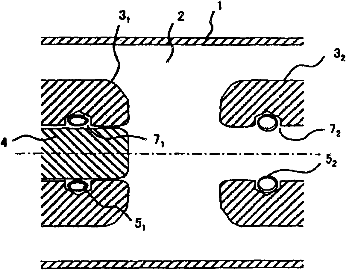
[0031] figure 1 is a cross-sectional view showing a switch using the coil-spring-shaped contact shoe in an off state according to the first embodiment.

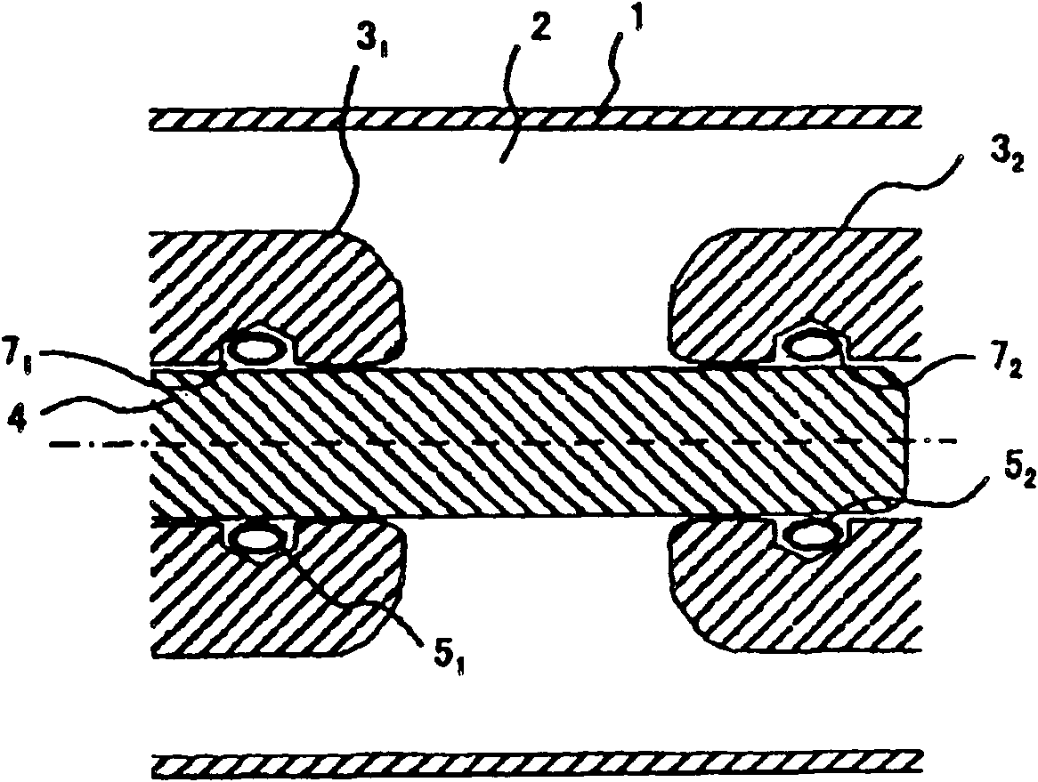
[0032] 0.4~0.6MPa SF 6 Gas is filled into the metal container 1 of the switch in order to ensure electrical insulation. Inside the metal container 1, the movable side contact part 3 1 and fixed side contact part 3 2 are arranged to face each other at predetermined intervals to form electrode portions (switch contact portions). And at the movable side electrode part 3 of one electrode constituting the electrode part 1 At , the cylindrical movable conductor 4 is slidably fixed. On the fixed side electrode part 3 of the other electrode constituting the electrode part 2 At , a cylindrical hollow body is provided for inserting the movable conductor 4 . First coil spring contact shoe 5 1 and a s...


PUM

PropertyMeasurementUnit
Tensile strengthaaaaaaaaaa

Abstract

A switch including a movable side contacting portion (3 1 ), a fixed side contacting portion (3 2 ) arranged to face the movable side contacting portion (3 1 ), a movable conductor (4) held slidably in the movable side contacting portion (3 1 ) which is to be inserted freely in the fixed side contacting portion (3 2 ), a first coil shaped contact shoe (5 1 ) loaded in a ring shaped groove (7 1 ) formed at an inner circumference of the movable side contacting portion (3 1 ), and a second coil shaped contact shoe (5 2 ) loaded in a ring shaped groove (7 2 ) formed at an inner circumference of the fixed side contacting portion (3 2 ). Here each of the first and the second coil shaped contact shoes (5 1 ,5 2 ) is a ring shape formed by jointing both ends of a coil spring at a joint portion (62 ), each of the joint portions (6 2 ) is located at an apex of an outer circumference of each of the first and second ring shaped contact shoes (5 1 ,5 2 ), and each of the first and second ring shaped contact shoes (5 1 ,5 2 ), contacts slope faces (8 2 ) formed at both sides of a bottom portion of the ring shaped groove (7 1 ,7 2 ).

Description

[0001] Cross References to Related Applications [0002] This application is based on and claims the benefit of priority from prior Japanese Patent Application No. 2009-127857 filed on May 27, 2009, which is incorporated herein by reference in its entirety. technical field [0003] The present invention relates to switches, and more particularly to switches using coil shaped contact shoes in the contact portions, for example, power switches and ground switches, among others. Background technique [0004] In a switch for a power supply device, a movable-side electrode and a fixed-side electrode are provided with inner conductors. And furthermore, a movable conductor slidably held in the movable electrode is provided, and a freely insertable portion of the movable conductor is provided in the fixed-side electrode so as to perform electrical switching. And many fine reed-like contact shoes are fixed to a sliding portion between the movable-side electrode and the movable conduc...

Claims


Application Information

Patent Timeline
IPC IPC(8): H01H1/44
CPCH01H1/06H01H33/64F16B21/183F16B21/186F16F1/045
Inventor 三轮郁夫矢永博纪
Owner KK TOSHIBA
Features
  • Generate Ideas
  • Intellectual Property
  • Life Sciences
  • Materials
  • Tech Scout
  • Unparalleled Data Quality
  • Higher Quality Content
  • 60% Fewer Hallucinations
Learn More